I-V Characteristics
Branch note: This page deepens one part of Current Electricity Fundamentals.
Overview
This note supports Current Electricity Fundamentals by focusing on the graph shapes that tell you whether a component is ohmic or non-ohmic.
Use it as the graph-reading layer on top of the hub, not as a replacement for the main definitions there.
Required syllabus set
You must be able to sketch and explain the – characteristics of a constant-temperature ohmic resistor, filament lamp, semiconductor diode, and NTC thermistor, as well as the resistance–temperature characteristic of an NTC thermistor.
Related topics:
Core Ideas
- An I-V characteristic shows how current through a component depends on the p.d. across it.
- Ohmic behaviour gives a straight line through the origin only when physical conditions, especially temperature, remain constant.
- Non-ohmic components have resistance that changes with operating point.
- For an ohmic straight-line -against- graph, the gradient is conductance, not resistance.
- For a non-ohmic curve, at the operating point; the local gradient gives differential conductance.
Exam Relevance
Questions often ask students to identify component behaviour from graph shape, calculate resistance at an operating point, or avoid confusing the gradient of an - graph with resistance.
Definition
An I-V characteristic is a graph showing how current through a component varies with potential difference across it.
Unless a question states otherwise:
- horizontal axis:
- vertical axis:
Always check the axes before you interpret gradient or curvature.
Why It Matters
These graphs help you see:
- whether a component obeys Ohm’s law
- whether resistance is constant
- how the component behaves as temperature, bias, or light level changes
- the current for a given voltage
Key Representations
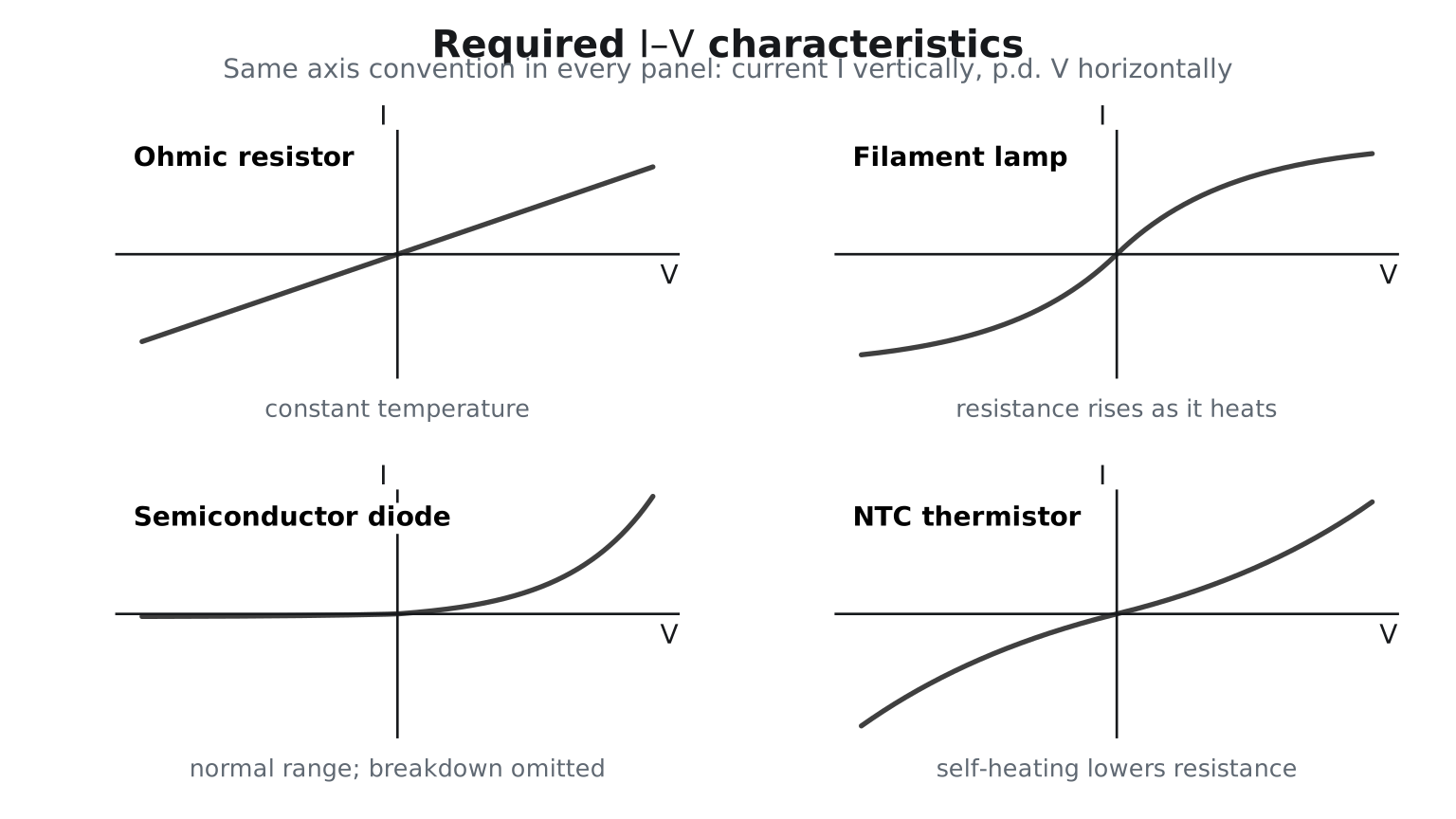
Figure: All four plots use current on the vertical axis and p.d. on the horizontal axis. The resistor is linear, the lamp curve is approximately symmetric and flattens as rises, the diode is strongly asymmetric, and the self-heating NTC curve is approximately symmetric and steepens as rises.
Ohmic Behaviour
A component is ohmic if, at constant temperature,
So the graph is a straight line through the origin and the resistance is constant.
For an ohmic conductor,
Non-Ohmic Behaviour
A component is non-ohmic if the graph is curved or asymmetric, or if the gradient changes with operating point.
Common examples:
- filament lamp
- diode
- thermistor
- LDR
Reading Resistance from a Graph
Resistance at a chosen point is still found from
Large means large resistance. Small means small resistance.
Gradient Meaning
For a straight-line ohmic -against- graph,
So:
- steeper line means lower resistance
- shallower line means higher resistance
For a curved non-ohmic graph, do not use the local tangent gradient as . The static or operating resistance at a chosen point is:
Enrichment: differential conductance
The tangent gradient is the differential conductance. It describes the response to a small change around that operating point; it is generally not for a curved graph.
If the graph is against ,
Component Patterns
Metallic Conductor
A metallic resistor at constant temperature obeys Ohm’s law and gives a straight line through the origin.
Filament Lamp
As current increases, the filament heats up. The temperature rise increases lattice vibrations, so collisions with electrons become more frequent and resistance rises.
The curve therefore becomes less steep as increases. Reversing the p.d. reverses the current but produces similar heating, so the characteristic is approximately symmetric about the origin.
Diode
A diode conducts much more easily in forward bias than in reverse bias.
Forward bias:
- current remains very small at low forward p.d.
- current then rises rapidly through a gradual knee as the junction barrier is reduced
Reverse bias:
- current is very small for normal reverse voltages
- resistance is very large
The often-quoted “turn-on voltage” is a useful approximation, not a perfectly sharp or universal threshold. Reverse breakdown is normally omitted from the introductory sketch unless a question asks for it.
Thermistor
For an NTC thermistor,
The dominant effect is that more charge carriers become available as temperature rises.
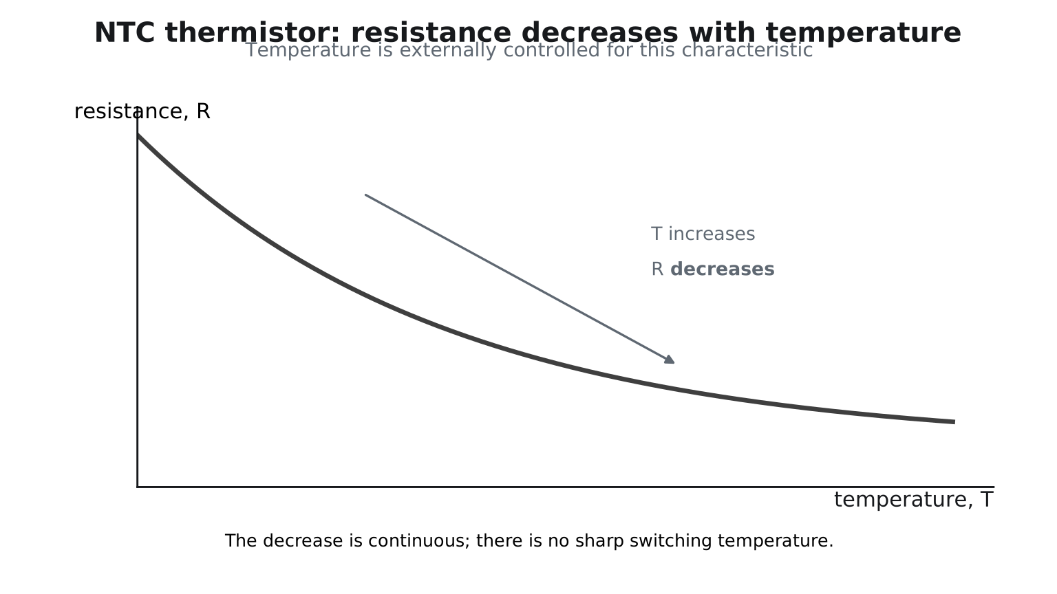
Figure: The – graph shows externally controlled temperature: resistance decreases continuously as temperature rises. On the – graph, increasing current can self-heat the thermistor, reducing resistance and making the curve increasingly steep. At a fixed temperature and for sufficiently small currents, an NTC thermistor is approximately ohmic.
LDR
Forward link to Topic 15
LDR behaviour is useful for potential-divider applications, but it is not one of the four component characteristics explicitly required in this topic’s syllabus outcome.
For an LDR,
More light creates more mobile charge carriers, so the resistance falls.
Worked Graph Reading
At a point where a component has and ,
This calculation uses the coordinates of the operating point. It does not use the tangent gradient of a curved characteristic.
Quick Checks
- Check the axis labels before using a gradient.
- Use for the resistance at a point.
- Do not assume every curve is a failure of Ohm’s law in the same way; the physical cause matters.
- Keep the graph reading tied back to the main hub page and the common-exam-traps note.