DC Circuits
Overview
This topic extends Current Electricity Fundamentals into complete direct-current circuits with sources, resistors, lamps, meters, dividers, and potentiometers.
The key skill is not just substitution into formulas. Students need to read the circuit first, then decide which local rule applies.
Main skills:
- read circuit symbols and component layouts
- analyse series, parallel, and mixed networks
- track current conservation at junctions
- track potential balance around loops and between nodes
- compare lamp brightness using power
- use divider logic for variable output and sensor circuits
- apply the potentiometer null method
- diagnose open-circuit, short-circuit, and meter-connection faults
Circuit Symbols and Diagram Reading
Symbol literacy matters because later circuit questions assume the diagram has already been interpreted correctly.
The core symbols in this topic include:
- cell or battery
- resistor
- lamp
- ammeter
- voltmeter
- variable resistor
- thermistor
- LDR
- switch
- galvanometer
- earth
- potential divider
Why this matters
The circuit shape controls which quantities are shared:
- series components share current
- parallel branches connected across the same two nodes share the same p.d.
- ideal wires share the same potential
 Circuit questions assume symbol fluency, so the first step is to recognize components, meters, and control elements quickly and accurately.
Core Ideas
DC-circuit analysis rests on a small set of ideas that recur throughout the topic:
- current is conserved at junctions
- potential difference is energy transferred per unit charge
- resistance controls how current and p.d. are distributed
- power determines heating and lamp brightness
- balanced potentials imply zero current in the null branch, not zero current in the whole circuit
Potential, Potential Difference, and Reference Nodes
Potential and potential difference should not be merged into one vague idea.
- Electric potential is a value assigned to a point in a circuit relative to a chosen reference point.
- Potential difference is the difference in electric potential between two points.
- In circuit energy terms, potential difference is the electrical energy transferred to other forms per unit charge as charge passes between two points:
- All points connected by an ideal wire are at the same potential, so there is no p.d. between them.
- A chosen reference node may be assigned , often called ground.
- What matters physically is not the absolute value of potential, but potential difference. Therefore, we are free to choose a convenient reference node; assigning it is the usual choice.
This is why potential-divider questions often ask for the potential of a point relative to the reference node, while energy-transfer questions often ask for the p.d. across a component.
Core Quantities
Current
Potential Difference
Notation Note: versus
Strictly, electric potential is a node value, while potential difference is the difference between two node potentials:
However, in circuit physics, it is conventional to use to denote the potential difference across a component or between two stated points:
This is a shorthand convention. Whenever appears in circuit formulae such as or , it usually means the p.d. across the component, not the absolute potential at one node.
A frequent source of confusion is that the same symbol is also sometimes used to denote the electric potential at a point. The meaning must therefore be read from context.
Resistance
For an ohmic conductor:
Power
Also:
Since
Exam Relevance
DC-circuit questions are usually won or lost on structure, not algebra. The key is to identify the network correctly, assign current and p.d. locally, and then apply the appropriate series, parallel, junction, or loop rule without treating formulas as global shortcuts.
Series and Parallel Circuits
Series
For components in series:
The same current flows through each component, while the total p.d. is shared across the chain.
Parallel
For components in parallel:
The same p.d. is across each branch, while the current splits between branches.
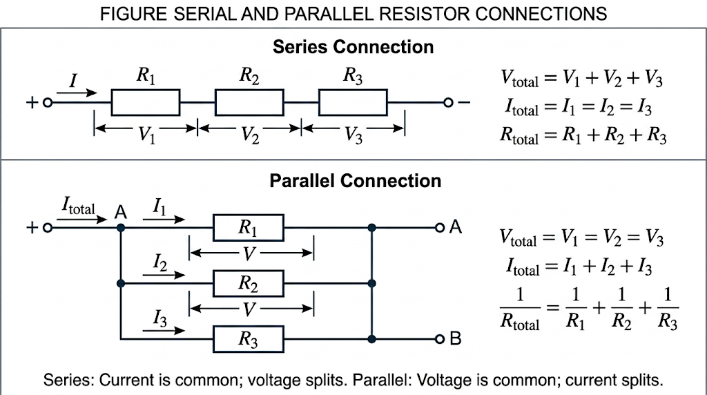
In series, current stays the same through the chain; in parallel, the p.d. stays the same across all branches.
Junctions and Loops
At a junction:
This is conservation of charge.
Around a closed loop, the potential rises and drops must balance. That is why divider and network questions often reduce to a small set of equations once the circuit is read correctly.
Mixed Networks
Most exam questions are not pure series or pure parallel. The key is to reduce them step by step.
Method
- identify an obvious series group
- identify an obvious parallel group
- replace one group with its equivalent resistance
- find the total current from the source
- work backwards to recover branch currents or p.d.s
Worked Example
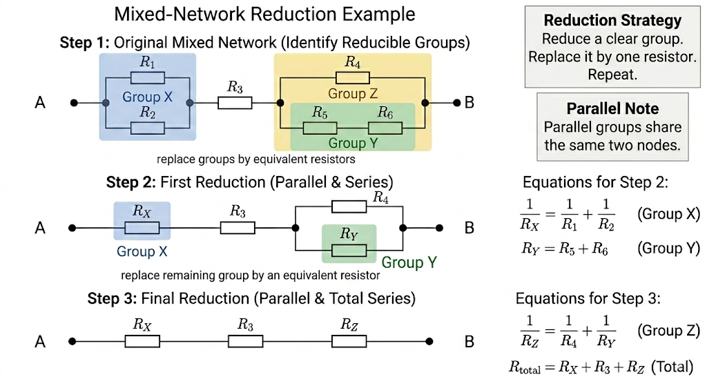 Reduce mixed networks step by step by replacing simple series or parallel groups with their equivalent resistances before working back to branch values.
## Brightness, Power, and Meter Rules
Reduce mixed networks step by step by replacing simple series or parallel groups with their equivalent resistances before working back to branch values.
## Brightness, Power, and Meter Rules
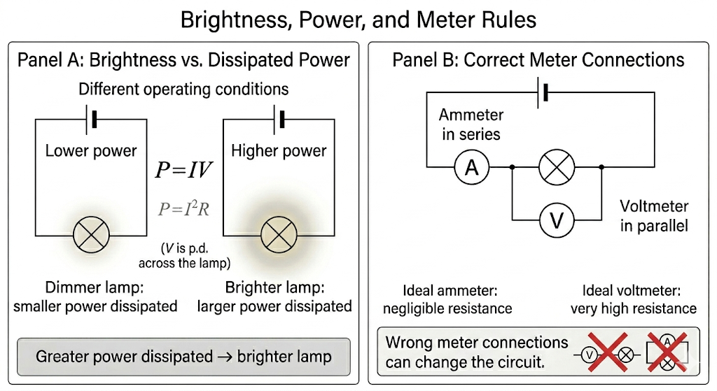
Lamp brightness depends on power dissipation, while ammeters and voltmeters must be connected in the correct way to avoid changing the circuit they measure.
Useful reminders:
- a brighter lamp is usually dissipating more power
- if the current changes, the lamp power usually changes too
- if the p.d. across a lamp changes, its power changes
- in a series fault, an open circuit can make the whole loop go dark
Meter rules:
- ammeter in series
- voltmeter in parallel
- ideal ammeter has negligible resistance
- ideal voltmeter has very high resistance
These rules matter because a wrongly connected meter can change the circuit, not just measure it.
Fault Finding
Fault-finding questions use the same laws as normal network questions. The difference is that one component or connection is wrong.
Open circuit
A break in the conducting path means:
- no current in that loop
- lamps in the same series loop go off
- a voltmeter across an intact component carrying no current may read if there is no p.d. across it
- a voltmeter across the broken component can read the full supply p.d.
Short circuit or bypass
A very low resistance path around a component means:
- current prefers the bypass
- the bypassed component gets little or no p.d.
- lamp brightness falls sharply
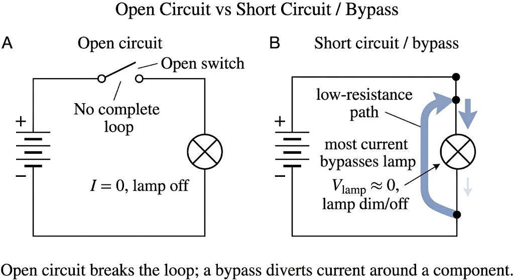 Open circuits break the conducting path, while short circuits provide a low-resistance bypass around the affected component.
Potential Dividers and Reference Potential
A potential divider is a series-resistor circuit that splits a supply p.d. in proportion to the resistances.
For two series resistors:
and:
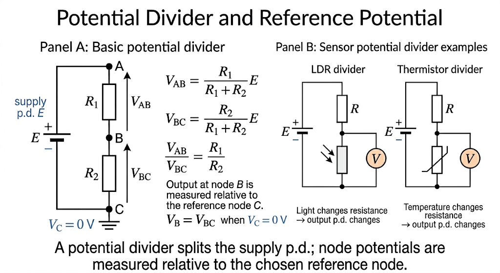 In a potential divider, the output p.d. is the fraction of the supply set by the resistance ratio and by the chosen output points.
Reference potential
- a node can be assigned a potential such as by grounding it
- p.d. is the difference between the potentials of two points
- all points on an ideal wire have the same potential
- a node can be positive or negative relative to the chosen reference
The output p.d. is the fraction of the supply set by the chosen resistor.
Potential-Distance Graph
Key interpretation:
- potential stays constant along ideal wires
- potential decreases across passive components in the direction of conventional current
- potential increases across a source such as a battery
- grounding one point sets the zero reference
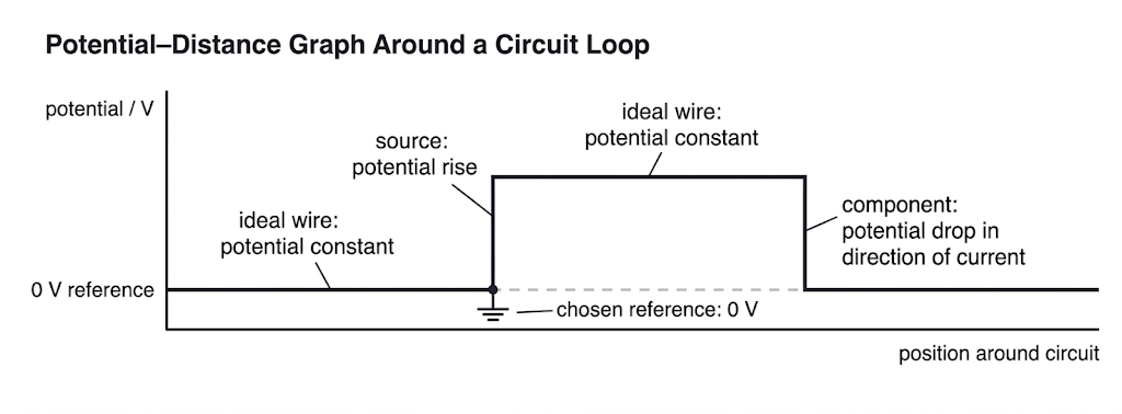 Potential stays constant along ideal wires, rises across sources, and falls across passive components in the direction of conventional current.
Variable-Resistor and Sensor Dividers
The divider output changes when one resistance changes.
This is the basis of variable-output circuits and sensor circuits.
See also Thermistors and LDRs.
Thermistor
Thermistor resistance decreases as temperature increases.
LDR
LDR resistance decreases as light intensity increases.
The exact p.d. change depends on where the sensor is placed in the divider:
- if the sensor is the output resistor, decreasing resistance may lower the output p.d.
- if the sensor is the other resistor, decreasing resistance may raise the output p.d.
That is why the circuit layout matters as much as the device identity.
Potentiometers
The potentiometer uses the null method.
A uniform wire carrying a steady current has a uniform potential gradient:
where is the potential gradient and is the balance length.
At balance:
- the galvanometer reads zero
- no current flows in the test branch
- the potentials at the two connected points are equal
This balances the unknown against a known wire drop instead of forcing current through the unknown cell.
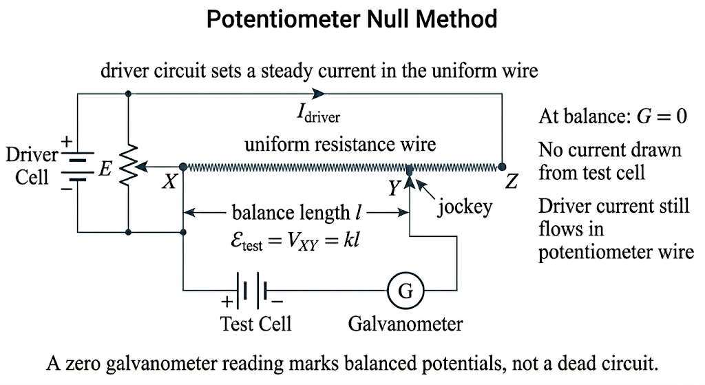 A zero galvanometer reading marks equal potentials at the balance points, so the null condition measures without drawing current from the unknown source.
Internal Resistance in Full Circuits
Real cells have internal resistance .
Terminal p.d. is:
So:
- larger load current gives larger lost volts
- terminal p.d. falls when current increases
See Internal Resistance.
Quick Revision Summary
- series: current same, p.d. shared, resistances add
- parallel: p.d. same, current splits, reciprocals add
- junction rule: current in equals current out
- loop rule: rises and drops balance
- brightness: compare power, not current alone
- divider: voltage share follows resistance share
- potentiometer: null method, balance length, potential gradient
- faults: open circuit breaks current; short circuit bypasses the component
Common Exam Traps
See DC Circuits Common Exam Traps for the compact checklist.
The most common mistakes are:
- calling two components parallel when they do not share both end nodes
- swapping the series and parallel rules for current and p.d.
- using the total supply p.d. for a single component in a series chain
- treating a potentiometer null as if the whole circuit carries no current
- forgetting that a voltmeter in series can disrupt the circuit