Current Electricity Fundamentals
Topic hub: This is the main overview page for Topic 13. Use it as the starting point, then follow the branch notes for deeper treatment of specific current-electricity subtopics.
Syllabus focus
The repository calls this Topic 13, while the 2026 H2 Physics 9749 syllabus lists this material under Topic 14, Current of Electricity. This note covers syllabus outcomes (a)–(k). Clearly marked enrichment sections are optional extensions.
Overview
Current electricity is the study of charge flow and energy transfer in electrical circuits. The core ideas here are the rate of flow of charge, the direction convention used for current, the difference between emf and potential difference, and the way real conductors and real sources depart from the ideal model.
This page is the primary teaching surface for Topic 13. Supporting pages deepen only selected subtopics.
The central causal chain is:
This topic focuses on:
- charge and current
- conventional current and electron flow
- potential difference and emf
- resistance and Ohm’s law
- I-V characteristics
- resistivity and geometry
- internal resistance and lost volts
- electrical power and appliance ratings
Related support notes:
- I-V Characteristics
- Internal Resistance
- Resistivity and Materials
- Electrical Power and Ratings
- Current Electricity Common Exam Traps
Core Ideas
- current is the rate of flow of charge
- conventional current follows the direction positive charge would move
- emf is energy supplied per unit charge by a source
- potential difference is energy transferred per unit charge between two points
- resistance is defined by the ratio , while Ohm’s law is the special proportionality for ohmic conductors at constant temperature
- real components can be non-ohmic
- resistance depends on material and geometry through resistivity
- real sources have internal resistance, so terminal p.d. can be less than emf
- power is the rate of electrical energy transfer
Exam Relevance
This topic is the foundation for later DC-circuit work. Most errors come from mixing up current direction, confusing emf with terminal p.d., applying Ohm’s law too broadly, or choosing the wrong power relation.
Charge and Current
Electric Charge
Charge is measured in coulombs, . The elementary charge is:
Charge can be positive or negative. In metals, the charge carriers are electrons.
Electric Current
Electric current is the rate of flow of electric charge through a cross-section:
More generally, the instantaneous current is:
For steady current:
Thus . Current tells us how much charge crosses a chosen section each second; it is not the speed of the charge carriers.
In a metal, conduction electrons already have rapid random thermal motion. With no applied electric field, crossings in opposite directions cancel on average, so the net current is zero. An applied p.d. establishes an electric field and adds a small average drift velocity to this random motion.
In circuit analysis, current is usually treated as a signed scalar. A positive current means that charge flow is in the chosen reference direction, while a negative current means that the actual conventional current is opposite to the chosen direction.
Link to Mobile Charge Density and Drift Speed
For a conductor with cross-sectional area , mobile charge carrier number density , charge magnitude per carrier , and drift speed :
Hence:
Here is measured in , in , in , and in . The units reduce to .
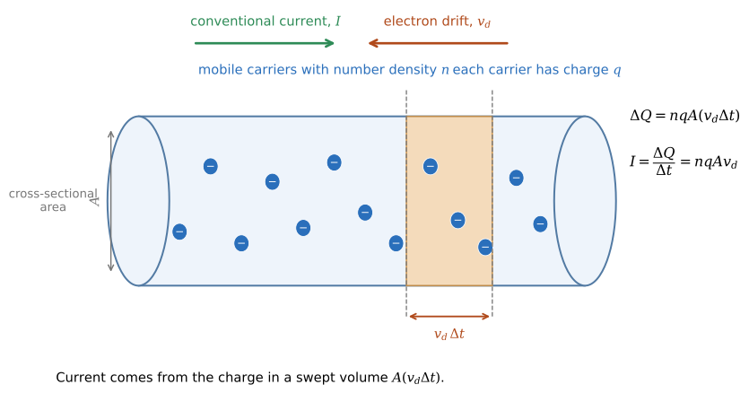
Figure: In time , carriers within a slab of length cross area . The slab contains carriers, so charge magnitude crosses and . A circuit responds before any one electron travels around it because the electric field is established throughout the circuit much faster than the slow drift.
This shows that current depends on how many mobile charge carriers are available, the charge magnitude carried by each carrier, the cross-sectional area of the conductor, and the average drift speed of the carriers.
For metals, the mobile charge carriers are electrons, but the conventional current direction is opposite to the direction of electron drift.
Conventional Current vs Electron Flow
Conventional current is defined as the direction positive charge would move. In a metal wire, electrons drift in the opposite direction.
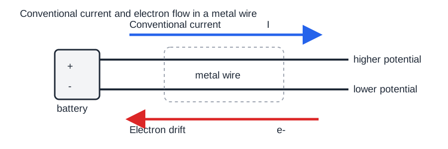
Figure: In a passive metal segment, conventional current is directed from higher to lower potential, while electron drift is opposite. The arrows show net drift, not the much faster random thermal motion.
In non-metallic media such as gases, electrolytes, and semiconductors, current can involve more than one kind of carrier. The current convention still does not change.
Positive carriers moving with conventional current and negative carriers moving oppositely both contribute conventional current in the same direction: reversing both charge sign and carrier velocity leaves the current direction unchanged.
Potential Difference and emf
Potential Difference
The potential difference between two points in a circuit is the electrical energy transformed to other forms per unit charge as charge passes from one point to the other:
where is the electrical energy transformed to other forms when charge passes between the two points.
So:
Electromotive Force
The electromotive force, or emf, of a source is the non-electrical energy transformed into electrical energy per unit charge passing through the source:
where is the work done by the source in transforming non-electrical energy into electrical energy.
It is a property of the source, not of the load.
emf vs Terminal p.d.
Potential difference can exist even when no current flows. When a real source supplies current, however, some energy supplied per coulomb is dissipated inside the source, so terminal p.d. is less than emf.
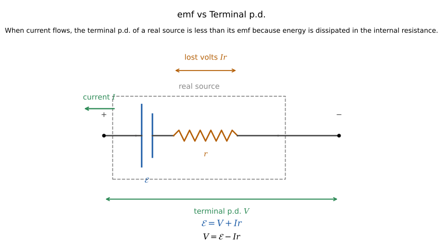
Figure: Each coulomb gains joules in the source. When the source supplies current, joules per coulomb are dissipated internally and joules per coulomb remain for the external circuit: .
Resistance and Ohm’s Law
Resistance
Resistance measures opposition to current flow:
Unit:
Ohm’s Law
For an ohmic conductor at constant temperature:
That means is constant, so:
That linear relation is not universal. It only holds for ohmic behaviour under the stated conditions.
I-V Characteristics
An I–V characteristic is a graph of current against potential difference . It shows whether a component is ohmic or non-ohmic, and how its resistance changes as operating conditions change.
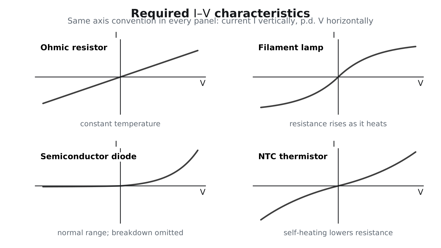
Figure: The vertical axis is current and the horizontal axis is p.d. A constant-temperature ohmic resistor gives a straight line. A filament lamp is approximately symmetric but becomes less steep as rises because its resistance rises. A diode conducts strongly in only one direction. An NTC thermistor self-heats, so its resistance falls and its curve becomes steeper.
Key patterns:
- metallic conductor at constant temperature: straight line through the origin; resistance is constant
- filament lamp: curve flattens as the filament heats up and resistance rises
- semiconductor diode: strongly asymmetric characteristic; forward current rises rapidly after a gradual knee, while normal reverse current is very small
- negative temperature coefficient thermistor: resistance falls as temperature rises
For any operating point, . Only for a straight ohmic – graph is the constant gradient equal to .
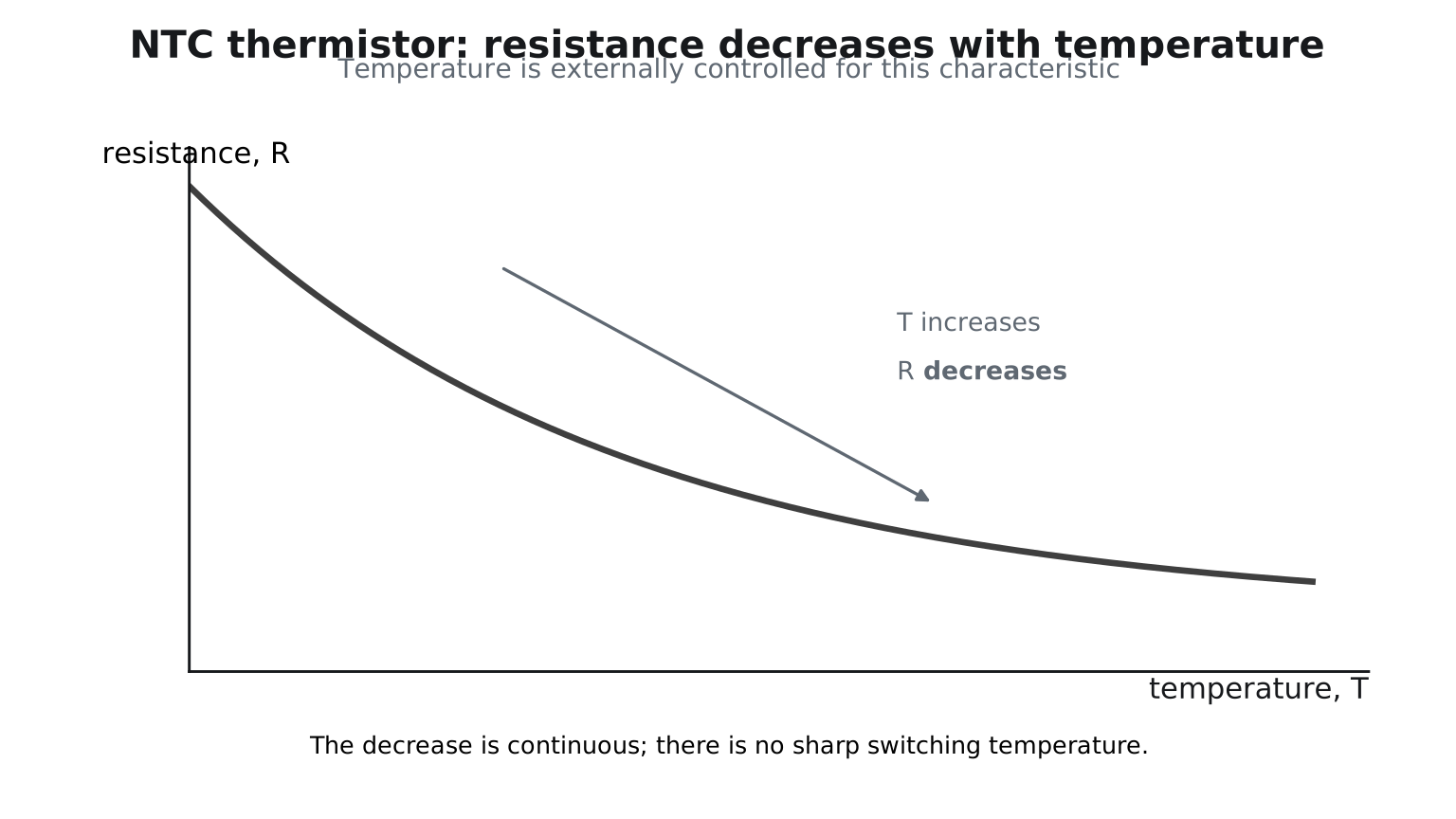
Figure: An NTC thermistor’s resistance decreases continuously as temperature rises. This externally controlled – graph is different from its self-heating – characteristic.
Resistivity and Geometry
For a uniform conductor of uniform cross-section at fixed temperature, resistance depends on both material and dimensions:
where:
- is resistivity
- is length
- is cross-sectional area
Longer wires have greater resistance; thicker wires have smaller resistance for the same material and temperature. For a circular wire, , so doubling the diameter makes the area four times larger and the resistance four times smaller.
Resistivity is a material property. It does not depend on the size of the sample, but it does depend on the material and temperature.
Internal Resistance
A real source has internal resistance . When the source supplies current :
so:
The quantity is the lost volts inside the source.
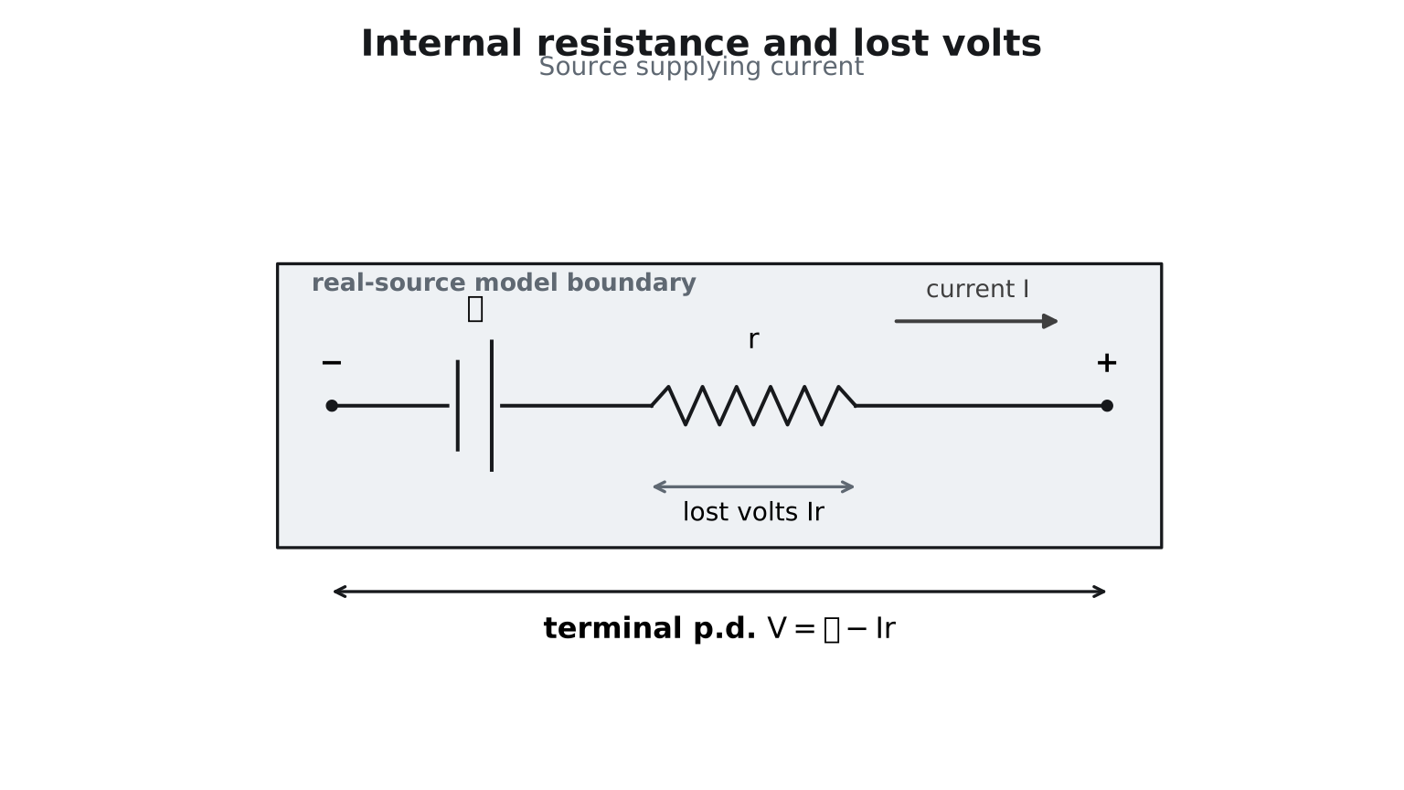
Figure: The lost volts are the p.d. across the internal resistance only, so the terminal p.d. between the source terminals is .
This model explains why:
- terminal p.d. falls when current rises
- sources heat up under load
- the open-circuit voltage can be close to the emf
- short circuits are dangerous
With an external load resistance ,
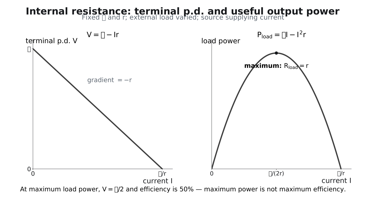
Figure: The terminal-p.d. graph has intercept and gradient . Useful output power is zero at open circuit, reaches a maximum when (equivalently ), and tends to zero in the ideal short-circuit limit. At maximum power the source efficiency is only ; maximum power is not maximum efficiency.
Electrical Power
Electrical power is the rate of electrical energy transfer:
This follows from , , and . It applies generally to electrical power transferred at an operating point.
For a resistor at its operating point:
and:
For a non-ohmic component, may change when voltage, current, or temperature changes. Do not assume one fixed resistance when comparing different operating points.
Energy transferred in time is:
For an appliance rating, the quoted power is the operating power when the appliance is connected to its rated potential difference.
Worked Examples
Drift Speed
A wire of cross-sectional area carries . Its mobile-electron number density is .
The small value reinforces that current is not a measure of how quickly an individual electron travels through the entire circuit.
Current from Charge Flow
If passes a point in :
Resistance
If a component has and :
Power
If a heater draws from a supply:
Internal Resistance
If , , and :
Exam Reasoning
When answering questions, check:
- what the quantity actually means
- whether the component is ohmic
- whether temperature is assumed constant
- whether the source is ideal or real
- whether the p.d. asked for is terminal p.d. or emf
- whether the correct power formula matches the known quantities
Common Exam Traps
- confusing emf with terminal p.d.
- treating Ohm’s law as universal
- reversing electron flow and conventional current
- mixing resistance and resistivity
- choosing the wrong power equation
- reading graph gradients without checking axis labels
For the compact trap sheet, see Current Electricity Common Exam Traps.
Quick Revision Summary
- Electric current: , and more generally
- For steady current:
- Potential difference:
- Electromotive force: for a source
- Resistance:
- Ohm’s law: , so is constant, for an ohmic conductor under constant physical conditions
- Resistivity:
- Electrical power:
- For resistive components:
- Energy transferred in time :
- Real source supplying current: