Capacitor Networks and RC Switching
Branch role: This enrichment page develops capacitor combinations, voltage continuity and simple RC switching after the Electric Capacitance hub.
Enrichment outside active 9749
Capacitor combinations and RC transients are retained for conceptual enrichment. They are not active 9749 learning outcomes.
Overview
Network questions become manageable when you identify the shared quantity before using a formula:
- parallel capacitors share the same p.d.;
- an ideal series chain prepared from initially uncharged capacitors has the same plate-charge magnitude on each capacitor;
- a capacitor’s p.d. cannot jump instantaneously unless an impulsive/infinite current is allowed;
- the resistance seen by the capacitor controls the transient timescale.
Core Ideas
- Parallel capacitors share p.d.; series capacitors in the ideal initially uncharged chain share plate-charge magnitude.
- Capacitor p.d. is continuous through ordinary switching: .
- Simple RC exponential formulae require constant , constant , ideal source/wires/switch, no leakage and a single energy-storage element.
- Time constants describe asymptotic approach to the final state, not an exact completion time.
Exam Relevance
This page is enrichment outside active 9749. If used locally, the main exam value is in identifying shared quantities, initial/final capacitor states, and the assumptions behind exponential charging or discharging formulae.
Parallel Capacitors
Capacitors connected across the same two nodes share p.d. . Define as the sum of the charge magnitudes delivered by the source to the corresponding plates connected to one supply terminal. This is not the algebraic net charge of the complete capacitor assembly. Then:
Therefore:
Series Capacitors
For an ideal series chain that begins uncharged, with electrically isolated and initially neutral intermediate conductors, charging induces equal charge magnitudes on the capacitors. The p.d.s add:
Hence:
Precharged capacitors or an externally connected intermediate node require explicit charge accounting; “same charge in series” is not a universal statement independent of initial conditions.
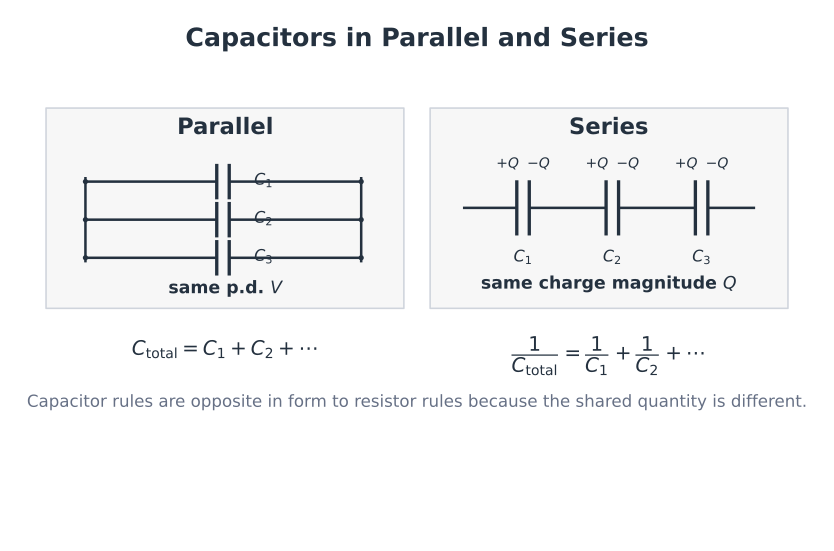
Figure: Parallel capacitors share two nodes and therefore the same p.d.; the source-delivered charge magnitudes on corresponding plates add when finding equivalent capacitance. This sum is not the algebraic net charge of the complete assembly. In the ideal initially uncharged series chain shown, neutral isolated intermediate nodes enforce a common plate-charge magnitude while the p.d.s add.
Exact Series Voltage Split
Two initially uncharged capacitors, and , are connected in series across .
The common charge magnitude is:
Thus:
The smaller capacitance has the larger p.d., and .
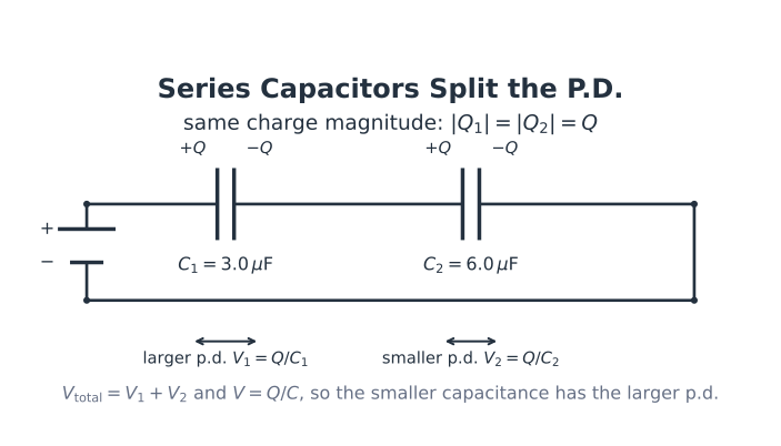
Figure: The exact example shows why series p.d. divides inversely with capacitance. Both capacitors carry , so the capacitor has while the capacitor has .
General Switching Workflow
For any ideal capacitor-switching question:
- determine the pre-switch steady state and find with its polarity;
- use voltage continuity, ;
- draw the post-switch circuit at and solve using the capacitor’s inherited voltage;
- draw the long-time steady-DC circuit with ideal capacitor branches carrying zero current, then find from the final node potentials—it need not equal the full source p.d. in a general network;
- only use the simple exponential formula if the post-switch circuit reduces to one effective - time constant.
The initially uncharged series example below is a special case, not the general rule.
Capacitor-Voltage Continuity
For a fixed capacitance, define as the p.d. of the labelled positive terminal relative to the other terminal and take as positive when it enters that positive terminal. With this passive sign convention:
An instantaneous finite jump in would require an impulse of current with unbounded magnitude in the ideal model. In ordinary resistor–capacitor switching circuits:
This is the safest starting rule. Do not automatically replace every capacitor with a short circuit at .
Initially uncharged simple series-RC circuit
If and a switch connects an ideal source through a resistor :
In this limited sense, the capacitor branch initially has zero capacitor p.d. and resembles a short-circuit limit.
After a long time with a steady DC source and an ideal leakage-free capacitor:
The capacitor then resembles an open circuit for steady DC. These are limiting comparisons, not claims that a capacitor physically becomes a wire or a broken connection.
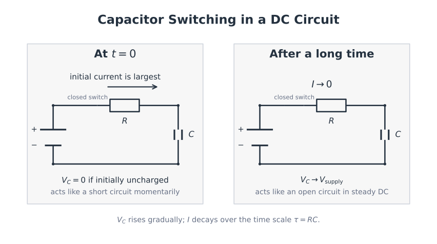
Figure: The same ideal series-RC circuit is shown just after closing and after many time constants. Voltage continuity plus the initially uncharged condition gives and ; at , current is approximately zero and is approximately .
Simple RC Exponential Model
The standard formulae below assume:
- one effective capacitance that remains constant;
- an ideal constant source for charging;
- a single linear resistance in the stated series path;
- a stated initial capacitor voltage;
- no leakage or additional energy-storage component.
The time constant is:
For discharge from through :
The current direction is opposite to the charging direction. Its magnitude is:
For charging from zero toward :
and:
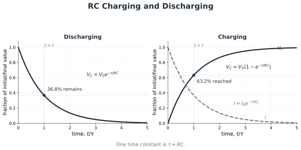
Figure: All curves are normalized exact exponentials. At , a decaying quantity has remaining and a charging voltage has reached of its final value. At , the remaining difference is , so the process is approximately—not exactly—complete.
Time-constant Landmarks
| Time | Charging fraction | Decaying fraction |
|---|---|---|
Worked Example
A capacitor discharges through from .
After :
The result is below the initial voltage and positive, as expected for a magnitude.
Common Misconceptions
- “Series always means equal charge.” State the initially uncharged/neutral-intermediate-node condition.
- “A capacitor’s voltage becomes zero immediately after any switch operation.” It retains its pre-switch voltage at .
- “A capacitor is literally a short circuit at first.” This is only a limiting comparison in specific circuits.
- “After the exponential is exactly zero.” It is approximately of its initial value.
- “The discharge current has the same sign as charging current.” Its direction reverses; use when plotting magnitude.