Circuit Fault Finding
Branch note: This page deepens one part of DC Circuits.
Overview
Circuit fault finding involves using current, potential difference and resistance principles to identify defective components or incorrect connections.
Typical faults tested in DC-circuit questions:
- open circuit
- short circuit
- broken lamp filament
- wrong meter connection
- loose connection
- unintended bypass path
- abnormal brightness behaviour
This topic supports DC Circuits.
Syllabus role
Fault finding is an application of the required skills of drawing, interpreting and analysing d.c. circuits. Use it to practise node, junction and loop reasoning; do not replace those core ideas with a list of memorised symptoms.
Core Ideas
- Fault finding is circuit analysis with one abnormal component or connection.
- An open circuit breaks a conducting path and can make current zero in that path.
- A short circuit provides a low-resistance bypass and can remove p.d. from the bypassed component.
- Meter readings must be interpreted together with circuit topology, not in isolation.
Exam Relevance
Fault-finding questions often test whether students can infer open circuits, short circuits, and wrong meter connections from current readings, voltmeter readings, and lamp brightness without guessing from a single clue.
Definition
Circuit fault finding is the process of inferring what has gone wrong in a circuit from current flow, potential-difference patterns, brightness changes, and meter readings.
Why It Matters
These questions test whether you actually understand circuit rules. Strong answers come from applying:
- current continuity
- voltage distribution
- resistance effects
- correct meter use
not from memorising outcomes.
Key Representations
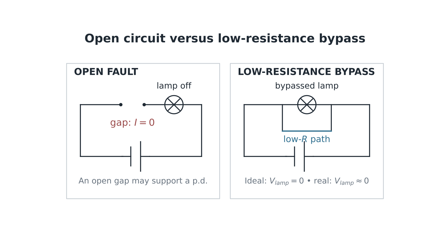
Figure: An open circuit breaks a conducting path; a short circuit provides a low-resistance bypass, so the fault must be inferred from current paths and p.d. readings together.
Core Diagnostic Strategy
When given a faulty circuit:
- Check whether current can complete a loop.
- Determine where current should flow.
- Determine where potential differences should appear.
- Compare expected lamp brightness or meter readings.
- Use all clues consistently.
Treat each question as a logic puzzle using circuit laws.
Open-Circuit Faults
Meaning
A break in the conducting path.
Examples:
- blown lamp filament
- disconnected wire
- open switch
- broken resistor connection
Consequences
- no current through that path
- lamps in that series path go off
- ammeter in that path reads zero
Open Circuit in Series
If one component fails open in a series circuit:
- entire loop current becomes zero
- all lamps in that loop go off
Voltage Behaviour
Across intact resistors:
Across the break, a non-zero p.d.—often the full source terminal p.d. in a simple one-loop circuit—may appear. This does not contradict zero current: an open gap is not an intact finite-resistance component to which can be applied using a finite .
Worked Example 1
Three lamps in series across a battery. One lamp fails open.
Result
- all lamps off
- current zero
- in this simple one-loop model, an ideal or high-resistance voltmeter across the failed lamp reads the source open-circuit terminal p.d.; this equals the emf for an ideal source
Open Circuit in Parallel
If one branch becomes open:
- that branch carries zero current
- other branches may continue normally
Example
Two lamps in parallel. One filament breaks.
- faulty lamp off
- other lamp still lights
Short-Circuit Faults
Meaning
A very low resistance path bypasses a component.
Examples:
- wire connected across lamp
- damaged insulation creating unintended connection
Consequences
- the two ends of an ideal-wire bypass are at the same potential
- a component connected across the same two nodes therefore has , so its current and power are zero
- for a very-low-resistance real bypass, the component p.d. is nearly zero, so it becomes very dim or goes off
- the supply current may become very large because the total circuit resistance falls; in reality it is limited by internal, wire and contact resistance
Worked Example 2
A wire is connected across a lamp.
Result
Potential difference across lamp becomes very small.
So lamp power decreases sharply and it goes dim or off.
Wrong Meter Connections
Ammeter Fault
Correct Use
Ammeter in series.
Wrong Use
Placed in parallel across source or component.
Because an ideal ammeter has zero resistance, and a real ammeter has very low resistance:
- very large current may flow
- circuit may short-circuit
Voltmeter Fault
Correct Use
Voltmeter in parallel.
Wrong Use
Placed in series.
Because an ideal voltmeter has infinite resistance, and a real voltmeter has very high resistance:
- current becomes very small
- lamps may not light
Brightness Symptoms
For comparable lamps, greater operating electrical power normally means greater brightness:
Unexpected brightness often indicates a fault.
A filament lamp is non-ohmic: its resistance changes with temperature. Compare its actual operating power rather than assuming that every lamp has a fixed resistance.
Examples
- dimmer than expected: reduced current, lower source emf, greater source internal resistance, or extra series resistance
- brighter than expected: larger p.d., fewer lamps in series
- lamp off: open circuit or bypass
Potential Difference Clues
Use voltmeter readings carefully.
Zero Reading Across Component
Possible causes:
- ideal wire connection
- short circuit
- no current through resistor in open-circuit system
Full Supply Reading Across Component
Possible causes:
- open break in a simple series path, under the usual ideal-meter assumptions
- component directly across source
Systematic Junction Reasoning
At a junction:
If one branch current becomes zero unexpectedly, suspect:
- open branch
- high resistance branch
- disconnected path
Worked Example 3
Two parallel lamps. Ammeter shows lower total current than normal, but one lamp still bright.
Likely Cause
The other branch is open circuit.
Reason:
- the working branch remains across the source terminal p.d.; this p.d. is unchanged only for an ideal fixed-voltage source
- total current reduced because one branch contributes zero current
Worked Example 4
Two identical lamps in series both become dimmer after a loose contact adds resistance to the loop.
Likely Cause
Extra resistance at contact reduces circuit current.
Both lamps carry the same reduced series current, so both have lower operating power and become dimmer. The poor contact also dissipates power.
Quick Fault Pattern Table
| Observation | Likely Fault |
|---|---|
| All lamps off, current zero | open main circuit |
| One parallel lamp off, other normal | open branch |
| Lamp unexpectedly off with wire bypass | short circuit across lamp |
| Current very large | short circuit |
| Comparable lamps very dim | lower source emf, greater source internal resistance, or added series resistance |
| Voltmeter in series gives weak circuit | wrong meter connection |
Common Exam Mistakes
1. Assuming One Broken Lamp Always Turns All Off
Only true in series loops.
2. Forgetting Zero Current Means Zero Voltage Across Resistor
Use:
3. Ignoring Meter Resistance
- ammeter low, voltmeter high
4. Looking at Only One Symptom
Use all clues together.
5. Ignoring Circuit Topology
Always decide whether circuit is series, parallel or mixed.
Fast Diagnostic Checklist
- Is there a complete conducting loop?
- Which components are in series or parallel?
- Should current exist here?
- Should p.d. exist here?
- Does brightness match expected power?
- Is any meter wrongly connected?
Links
Summary
Circuit fault finding is mostly careful application of:
- current continuity
- loop voltage reasoning
- resistance effects
- power and brightness logic
- correct meter behaviour
Strong students solve these questions systematically instead of guessing.