Potentiometer
Branch note: This page deepens one part of DC Circuits.
Overview
A potentiometer is a circuit used to measure or compare emf and potential difference accurately using the null method.
Instead of reading voltage directly from a meter, an unknown source is balanced against the potential drop along a uniform wire carrying current.
Main uses:
- compare emf of cells
- measure unknown emf
- measure potential difference accurately
- determine internal resistance of a cell
This topic supports DC Circuits.
Syllabus focus
The required principle is comparison of potential differences by balance lengths. Internal-resistance measurement is retained later as a clearly marked cross-topic enrichment application.
Core Ideas
- A potentiometer uses a uniform wire carrying steady current to produce a uniform potential gradient.
- At balance, the galvanometer reads zero because the two connected points are at the same potential.
- No current is drawn from the test cell at balance, so the measured value is the emf rather than a loaded terminal p.d.
- Balance lengths can compare emfs or help determine internal resistance.
Exam Relevance
Potentiometer questions often test the null condition, the meaning of potential gradient, emf comparison by balance-length ratio, and the distinction between zero current in the galvanometer branch and current in the main potentiometer wire.
Definition
A potentiometer is a null-method circuit that measures or compares emf by balancing it against the potential drop along a uniform wire.
Why It Matters
The potentiometer matters because it:
- measures emf without drawing current from the test cell at balance
- compares emfs accurately
- supports internal-resistance measurements
- makes voltage measurement depend on length rather than meter calibration
Key Representations
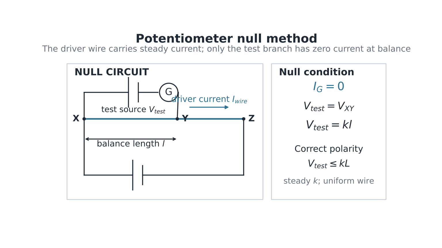
Figure: The test source is connected so that its p.d. opposes the potential fall along the wire from its high-potential end. At balance the galvanometer terminals are at equal potential, so ; current still flows in the driver wire.
Core Principle
A long uniform resistance wire carries a steady current.
Because the wire has:
- uniform material
- constant cross-sectional area
- constant temperature and hence uniform resistance per unit length
- steady current
the potential drop is proportional to length.
Hence:
where:
- = potential gradient (V m)
- = length measured along the wire
If the total wire resistance is and its length is ,
Potential Gradient
If a wire of total length has p.d. across it:
So over any length :
This converts voltage measurement into length measurement.
Null Method
An unknown cell is connected through a galvanometer to a sliding contact (jockey) on the wire.
The jockey is moved until galvanometer shows zero deflection.
At balance:
- no current flows through the galvanometer and test cell
- potential difference across galvanometer is zero
- for an emf measurement, the unknown emf equals the wire p.d. over the balancing length
The test source polarity must oppose the wire p.d. over the balance length. Reversing it makes the two p.d.s reinforce, so no null point is obtained.
The maximum p.d. available for balance is the drop across the full wire:
If the unknown p.d. exceeds , its calculated balance length lies beyond the physical wire and no balance point exists.
Why Null Method Is Accurate
At balance, no current is drawn from the unknown cell through the galvanometer branch.
Therefore:
- no lost volts inside the cell during measurement
- the measured value equals the emf in the ideal null model because the test cell supplies no current
- galvanometer only detects balance, not magnitude
This is often more accurate than using a voltmeter.
Basic Circuit Components
A typical potentiometer setup includes:
- driver cell or power supply
- rheostat (to control current)
- long uniform wire
- jockey
- galvanometer
- switch
- test cell
Comparing emfs of Two Cells
If two cells balance at lengths and using the same wire current:
Hence:
No need to know explicitly.
More generally, if two potential differences and balance at and while the same wire current is maintained,
This is the syllabus’s general “comparing potential differences” principle.
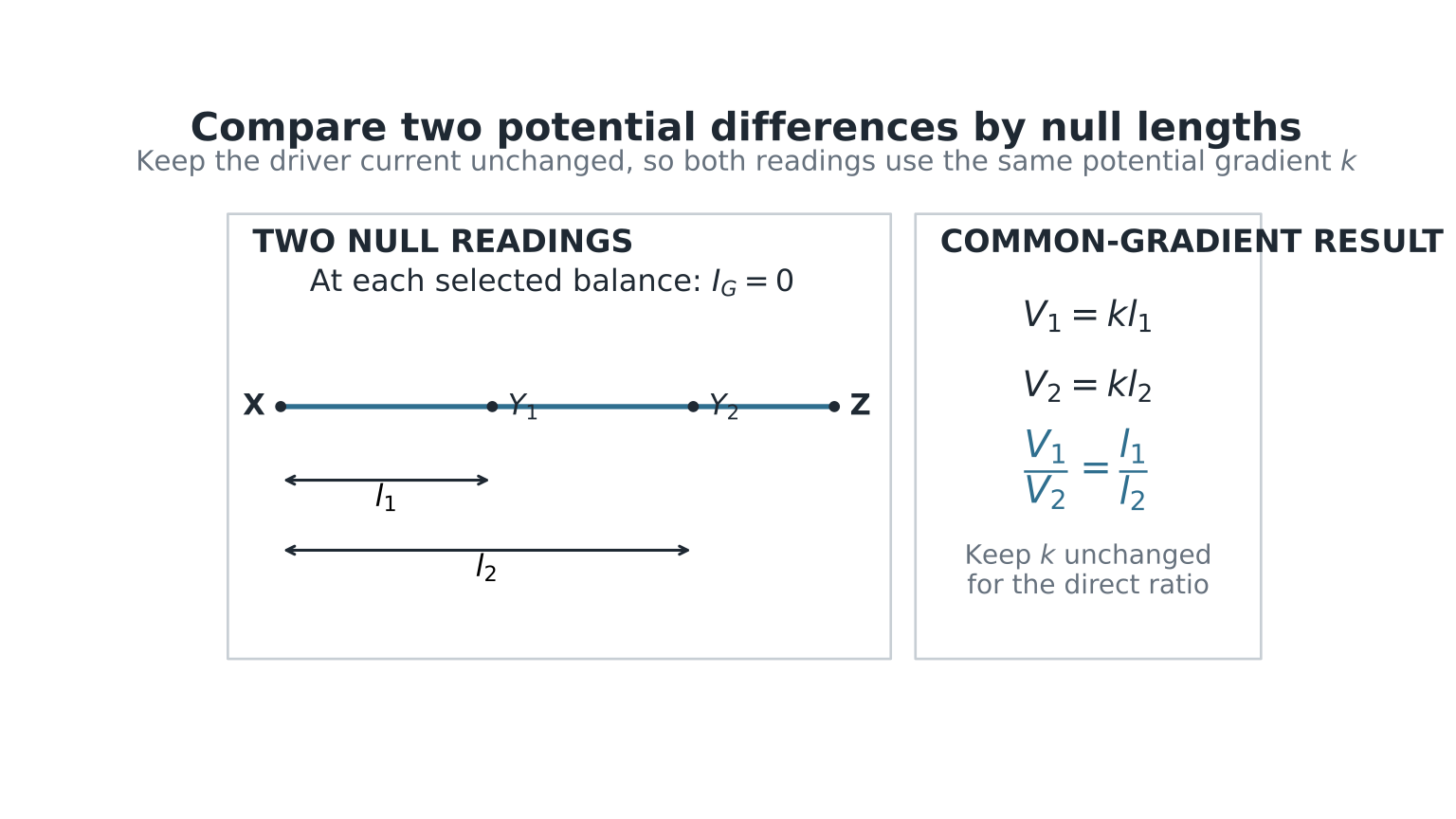
Figure: Both balance readings must use the same unchanged driver current, so the potential gradient is common. Each test branch carries zero current at its own null; the ratio of the p.d.s therefore equals the ratio of the balance lengths.
Worked Example 1
Two cells balance at lengths:
If , find .
Measuring Unknown emf
If gradient is known and balance length is :
Worked Example 2
Wire length has p.d. across it.
Balance length of unknown cell:
Step 1: Gradient
Step 2: emf
Measuring Internal Resistance of a Cell
Enrichment/application: combining the potentiometer with internal resistance
This is a useful synthesis with Current of Electricity, but it is not explicitly named in the Topic 15 potentiometer outcome.
See also Internal Resistance.
Method
Measure:
- emf with cell not supplying current
- terminal p.d. when current flows through an external resistor
Let be the open-circuit balance length for emf . Connect a known load across the cell and obtain loaded balance length for terminal p.d. . Keep the driver current and hence unchanged.
Using balance lengths:
The load current is , and . Therefore
For example, if , , and ,
Why Zero Galvanometer Current Matters
If no current flows through the galvanometer and test-cell path at balance:
- no energy is transferred in that path during measurement
- galvanometer reads zero
- galvanometer/test-branch resistance does not alter the exact balance condition because its current is zero, although it can affect sensitivity while approaching balance
This is the essential advantage of potentiometers.
Practical Reasoning
If Wire Current Increases
Potential gradient increases.
So the same emf balances at a shorter length.
If Unknown emf Increases
Longer balancing length is required.
Range–Sensitivity Trade-off
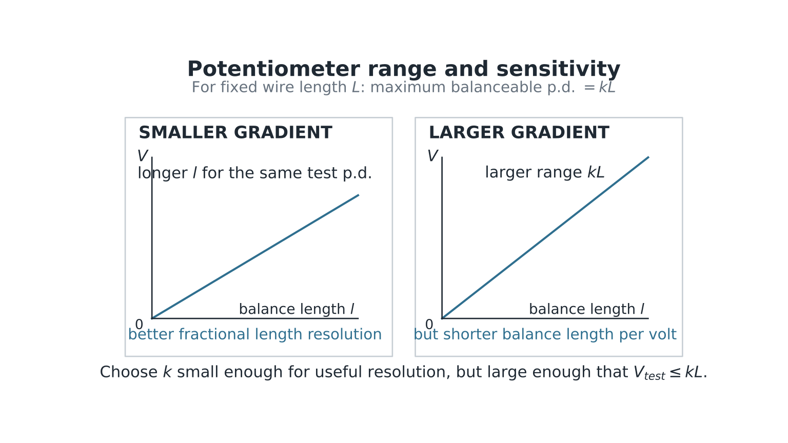
Figure: For a fixed wire length, reducing produces a longer balance length for each volt, improving fractional length resolution, but it also lowers the maximum balanceable p.d. . A useful setting must provide both adequate range and a comfortably long balance length.
If No Balance Point Is Found
Check two distinct causes:
- wrong polarity: the test p.d. reinforces rather than opposes the wire drop;
- insufficient range: .
Changing the driver current changes . Balance-length ratios may be compared directly only when both readings use the same potential gradient.
Common Exam Question Types
1. Compare Two Cells
Use:
2. Find Unknown emf
Use:
3. Determine Internal Resistance
Use open-circuit and loaded balance lengths.
4. Explain Zero Deflection
Balanced potentials produce zero p.d. across galvanometer.
Common Mistakes
1. Thinking No Current Flows Anywhere
Only the galvanometer/test-cell path has zero current at balance. Current still flows in the main potentiometer wire.
2. Wrong Ratio Direction
Larger emf gives larger balancing length.
3. Confusing emf with Terminal p.d.
Loaded cell may not give full emf.
4. Ignoring Need for Uniform Wire
Linear relation depends on uniform wire.
5. Ignoring Polarity or Range
A correct circuit can still have no balance point if the test source is reversed or if its p.d. exceeds the full-wire drop.
Quick Comparison Table
| Quantity Increased | Effect |
|---|---|
| Unknown emf | longer balance length |
| Wire current | larger gradient |
| Wire current | shorter balance length for same emf |
Links
- DC Circuits
- Potential Divider
- Internal Resistance
- Circuit Fault Finding
- DC Circuits Common Exam Traps
Summary
A potentiometer is a precise null-method device that balances an unknown emf against the voltage drop along a uniform wire.
Key ideas:
- potential drop proportional to length
- zero galvanometer deflection at balance
- no current drawn from test cell at balance
- excellent for emf comparison and internal resistance measurement
This is one of the most elegant DC-circuit techniques in H2 Physics.