Potential Divider
Branch note: This page deepens one part of DC Circuits.
Overview
A potential divider is a circuit arrangement that uses resistors in series to divide an input voltage into smaller output voltages.
It is one of the most important DC-circuit ideas because it allows:
- adjustable output voltage
- sensor circuits
- reference voltages
- control systems
This topic supports DC Circuits.
Conditions for the basic rule
means the actual p.d. across the two series resistors. The simple formula initially assumes no load draws current from the output. It is equal to a source emf only for an ideal source or when internal resistance is negligible.
Core Ideas
- A potential divider is a series circuit, so the same current flows through the divider resistors.
- The p.d. across a chosen resistor is proportional to its resistance.
- The output p.d. depends on the two output points, not just on the component name.
- Sensor dividers convert a changing resistance into a changing output p.d.
Exam Relevance
Potential-divider questions often test whether students choose the correct numerator in the divider formula and whether they can predict output trends when a thermistor, LDR, or variable resistor changes value.
Definition
A potential divider is a series-resistor arrangement that produces an output potential difference equal to a chosen fraction of the input voltage.
Why It Matters
Potential dividers are one of the main ways circuits convert:
- a fixed supply into a chosen output voltage
- a changing resistance into a measurable electrical signal
- temperature, light, or position changes into voltage changes
Key Representations
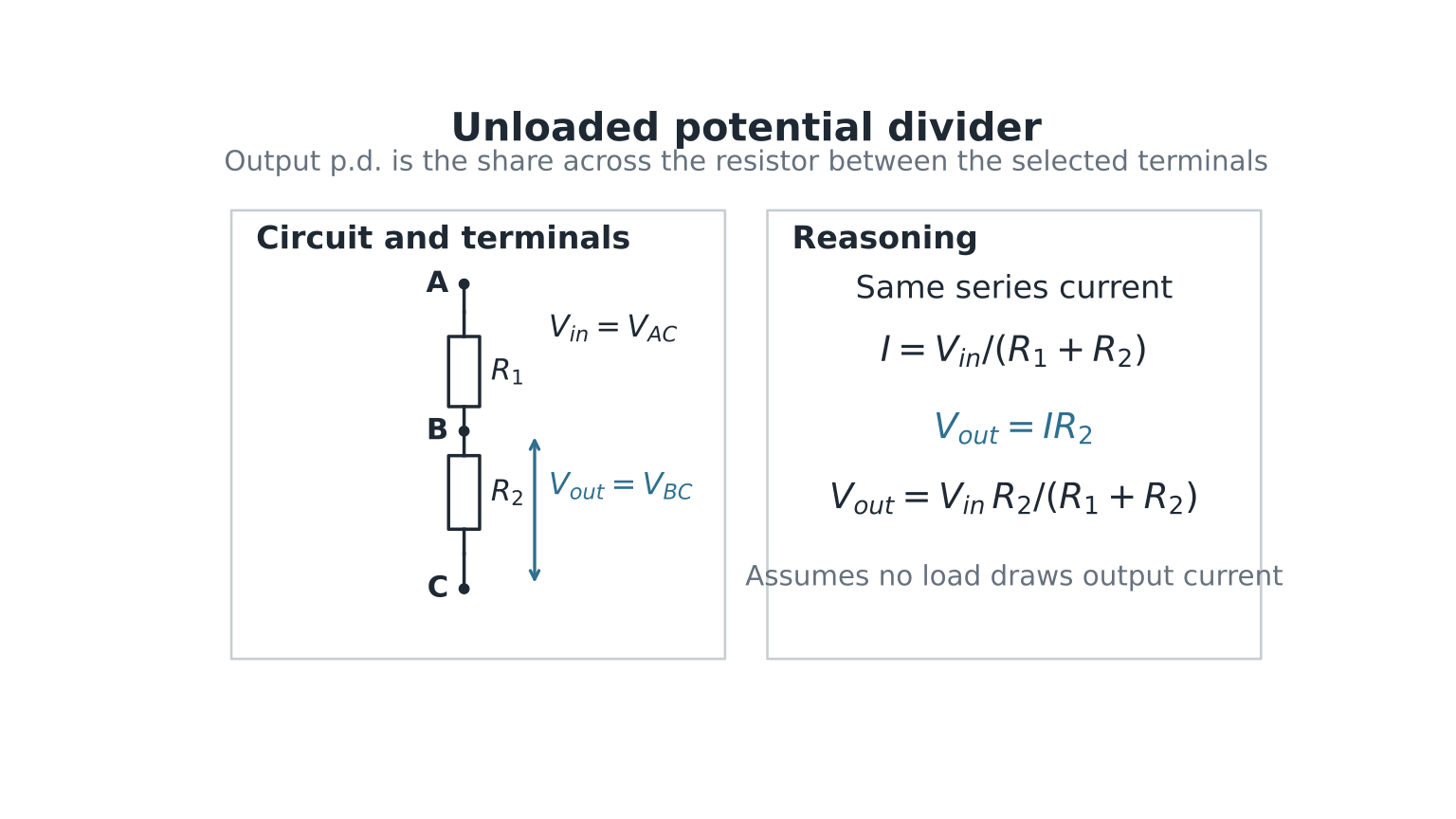
Figure: In an unloaded divider, the same current flows through both resistors. The output p.d. is measured between two stated terminals, so the numerator is the resistance lying between those terminals, not a memorised “top” or “bottom” resistor.
Divider Principle
For resistors connected in series:
- the same current flows through each resistor
- total potential difference equals the sum of voltage drops
Since:
a larger resistance gets a larger share of the voltage.
Two-Resistor Potential Divider
Two resistors and connected in series across input voltage .
Total Resistance
Current
Voltage Across Each Resistor
Output Voltage Relation
If output is taken across :
This is the standard divider equation.
It also passes two useful limiting checks:
- if , then ;
- if , then .
Ratio Form
For two series resistors:
Useful for fast mental checks.
Variable Divider
Replace one resistor with a variable resistor.
Changing resistance changes:
Common Uses
- volume controls
- brightness adjustment
- tuning knobs
- calibration controls
A two-terminal variable resistor used to control current is a rheostat. A three-terminal component used to select a fraction of a fixed p.d. is also commonly called a potentiometer or variable potential divider. Do not confuse this component use with the null-method potentiometer experiment in the next branch note.
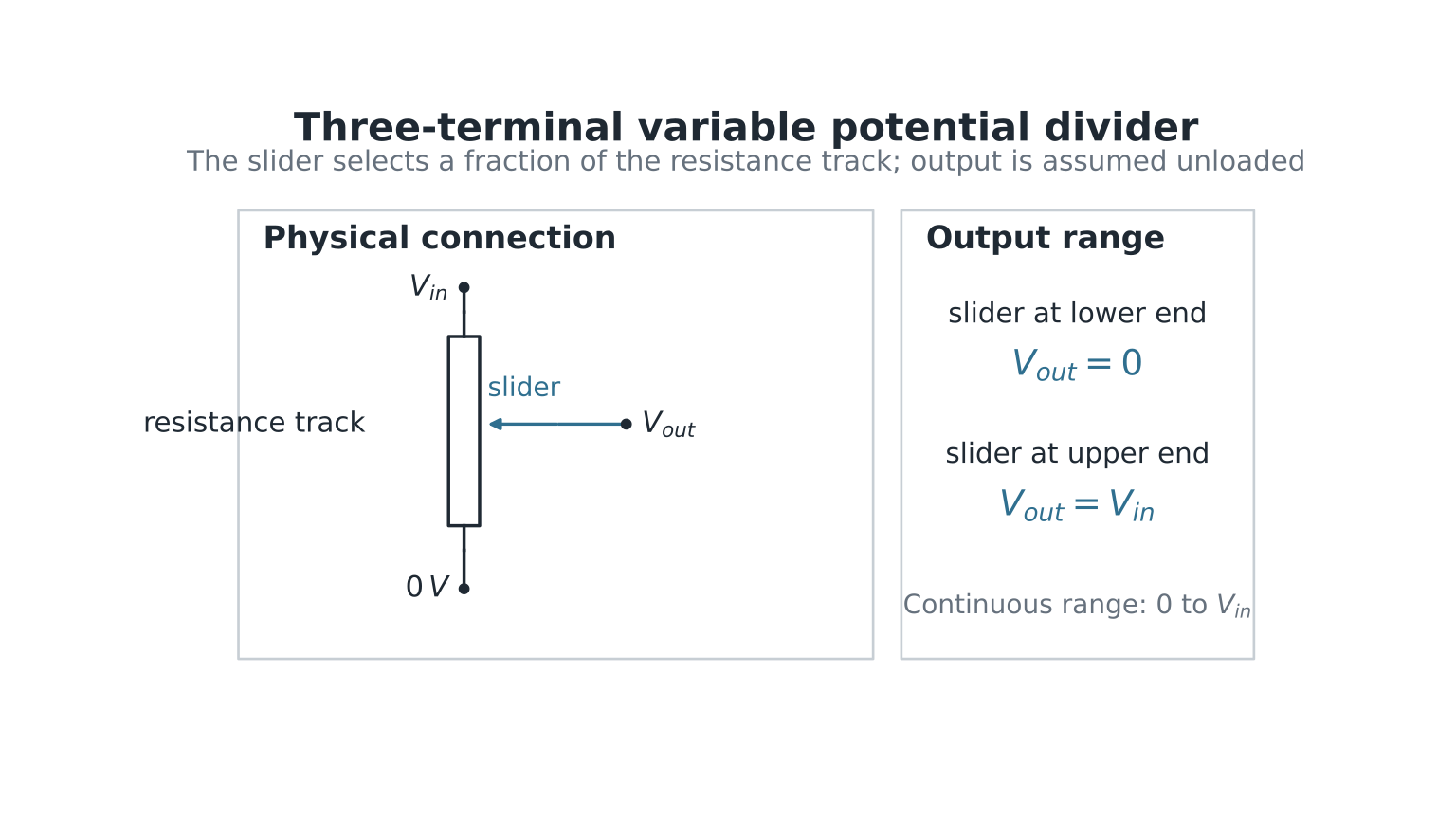
Figure: A sliding contact divides the resistance track into two series parts. For an unloaded output measured from the slider to the lower end, moving the slider changes the selected resistance fraction and hence varies continuously from to .
Sensor Applications
Potential dividers convert changing resistance into changing voltage.
Thermistor Divider
See also Thermistors and LDRs.
For a common NTC thermistor:
- temperature increases
- resistance decreases
Hence output voltage changes with temperature.
Uses
- thermostat circuits
- temperature alarms
- temperature sensing
LDR Divider
For an LDR:
- light intensity increases
- resistance decreases
Hence output voltage changes with light level.
Uses
- automatic street lighting
- camera light sensing
- security systems
Position Matters
Whether output rises or falls depends on where the sensor resistor is placed.
Example
If output is measured across lower resistor:
- lower resistance increases output increases
- lower resistance decreases output decreases
Always inspect circuit arrangement.
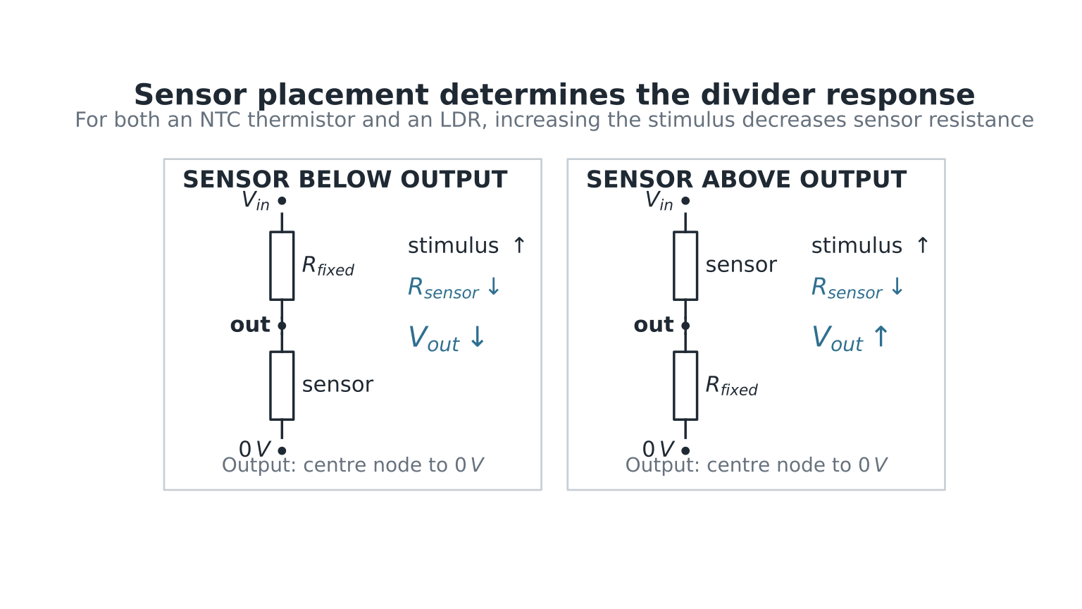
Figure: For output from the centre node to , . An NTC thermistor or LDR decreases in resistance when its stimulus increases. If it is below the output node, falls; if it is above, rises.
The fixed resistor is essential: together, the fixed resistor and sensor form the series pair that turns a resistance change into a p.d. change.
Loaded and Unloaded Divider
Enrichment/application: loading
Loading is useful for real measurement circuits but is not the central statement of the potential-divider syllabus outcome.
Unloaded Divider
No device draws current from output.
Standard divider formula applies directly.
Loaded Divider
Output connected to another component drawing current.
Then:
- effective resistance changes
- the original unloaded-divider formula no longer applies directly
- if the load is connected across the output resistor, the output p.d. is usually lower than the unloaded value
If a load is placed across , replace the lower arm by
Then
Because , loading lowers the output in this arrangement. Many core questions assume an unloaded divider unless stated otherwise.
Loaded-divider example
Let , , , and . Unloaded, . Loaded,
Worked Example 1
Two resistors and connected across supply.
Output taken across resistor.
Worked Example 2
A thermistor forms the lower resistor in a divider.
Temperature rises, thermistor resistance decreases.
Result
Output across thermistor:
As decreases:
If the same thermistor were the upper resistor and the output were still measured across the lower fixed resistor, the decrease in upper resistance would instead make increase.
Worked Example 3: Find an Unknown Resistance
An unloaded divider has , upper resistance , and across the lower resistor .
where resistances are in . Hence
The answer is sensible because the output is less than half the input, so the lower resistance should be smaller than the upper resistance.
Common Exam Question Types
1. Calculate Output Voltage
Use divider formula directly.
2. Predict Direction of Change
Determine how resistance changes.
3. Design Sensor Circuit
Choose resistor positions so output increases or decreases as required.
4. Determine Unknown Resistance
Rearrange formula algebraically.
Common Mistakes
1. Using Parallel Formula
Potential dividers use series resistors.
2. Wrong Numerator
Use the resistor across which output is measured.
3. Assuming Equal Split
Voltage divides equally only if resistances are equal.
4. Ignoring Sensor Position
Top and bottom placement changes behaviour.
5. Forgetting Units
Use volts for output.
Quick Comparison Table
| Situation | Output Across Lower Resistor |
|---|---|
| Lower resistance increases | increases |
| Lower resistance decreases | decreases |
| Upper resistance increases | decreases |
| Upper resistance decreases | increases |
Links
- DC Circuits
- Current Electricity Fundamentals
- Potentiometer
- Circuit Fault Finding
- DC Circuits Common Exam Traps
Summary
A potential divider converts a fixed input voltage into a controlled output voltage.
Key ideas:
- same current in series
- voltage share proportional to resistance
- changing resistance changes output voltage
- useful for sensors and controls
Master this topic well because it appears frequently in H2 circuit questions.