Semiconductors and Diodes
Overview
This hub collects the observable semiconductor behaviours required for H2 Physics: diode current-voltage behaviour, NTC thermistor characteristics, LDR/thermistor sensing circuits, and single-diode half-wave rectification.
Scope guide
The core syllabus requirements in this topic are:
- sketch and explain the qualitative current–voltage characteristics of a semiconductor diode and an NTC thermistor;
- sketch the resistance–temperature characteristic of an NTC thermistor;
- explain thermistor and LDR potential-divider circuits;
- explain single-diode half-wave rectification.
Detailed energy-band theory, depletion-layer modelling, semiconductor doping and microscopic p–n-junction theory are not required here. A short carrier explanation is retained only to support the observed trends. Bridge rectification, smoothing capacitors and LEDs are labelled enrichment.
1. Why these components matter
An ordinary fixed resistor is often modelled by one constant resistance. Semiconductor components can behave very differently: their current or resistance may change strongly when voltage, temperature or illumination changes.
The useful reasoning pattern is
Core Ideas
- Semiconductor components are assessed mainly through observable characteristics and circuit effects.
- Diodes conduct much more readily in one direction than the other.
- NTC thermistors and LDRs have resistance trends that can be used in potential dividers.
- Single-diode rectification gives unidirectional but time-varying output.
- Microscopic p-n-junction theory, bridge rectification and smoothing are enrichment unless supplied by a question.
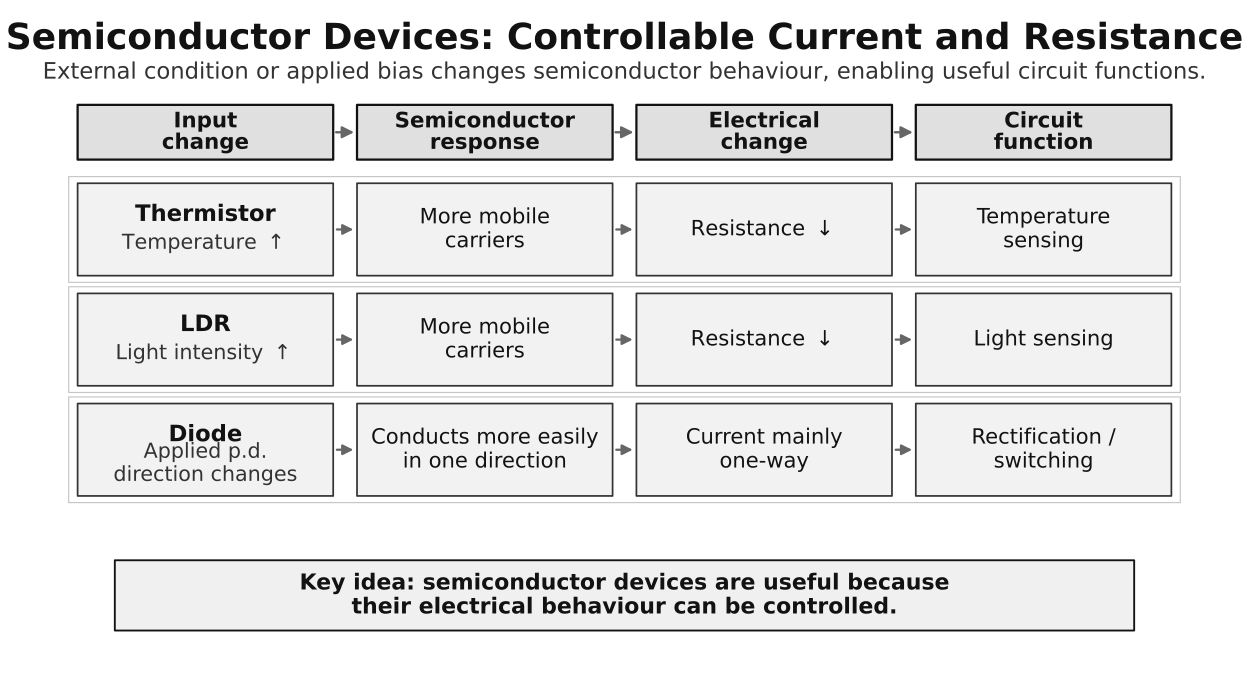
Figure: Temperature, illumination and applied p.d. affect different semiconductor components. The figure is a map of observable trends, not a claim that all devices respond to every input in the same way.
2. Conductors, insulators and semiconductors
| Material class | Qualitative conductivity | First-learner picture |
|---|---|---|
| conductor | high | many mobile charge carriers are already available |
| insulator | very low under normal conditions | very few mobile carriers are available |
| semiconductor | intermediate and strongly controllable | the number of mobile carriers can change substantially |
Semiconductors are not merely “halfway” materials. Their important feature is control: temperature, illumination or device bias can change how readily current flows.
Qualitative carrier explanation
Electric current requires mobile charge carriers. In a semiconductor, mobile electrons and effective positive carriers called holes may contribute.
A hole is not a proton travelling through the material. It is the effective positive carrier associated with a missing electron in the bonding structure.
For a fixed component and applied p.d., a larger mobile-carrier density generally allows a larger current:
This is a qualitative explanation only. Detailed carrier statistics and p–n-junction structure are enrichment beyond the required model.
3. Four different characteristics
Do not confuse these graphs:
- a diode current–voltage characteristic, against ;
- an NTC thermistor current–voltage characteristic, against ;
- an NTC thermistor resistance–temperature characteristic, against temperature;
- an LDR resistance trend with illumination.
Always read both axes before explaining a curve.
4. The semiconductor diode
A diode is a two-terminal component that conducts far more readily in one direction than the other. Its circuit symbol fixes the permitted conventional-current direction in the ideal model.
Reference convention
Choose the diode p.d. as positive for the forward-bias polarity and current as positive in the forward direction. With this convention:
- positive : forward-bias region;
- negative : reverse-bias region.
If a question defines the axes differently, follow the question’s convention rather than memorising a left/right position.
Forward bias
In forward bias, current is initially small. Beyond a turn-on region, a small further rise in p.d. produces a rapid increase in current.
For a silicon diode, about – is sometimes used as an approximate conducting drop, but it is not a universal exact threshold. Use the ideal-diode model or numerical value specified by the question.
Reverse bias
In the ordinary reverse-bias range used in this syllabus, current is treated as negligible. Reverse breakdown is outside the simple model unless a question explicitly supplies it.
5. Reading the diode I–V characteristic
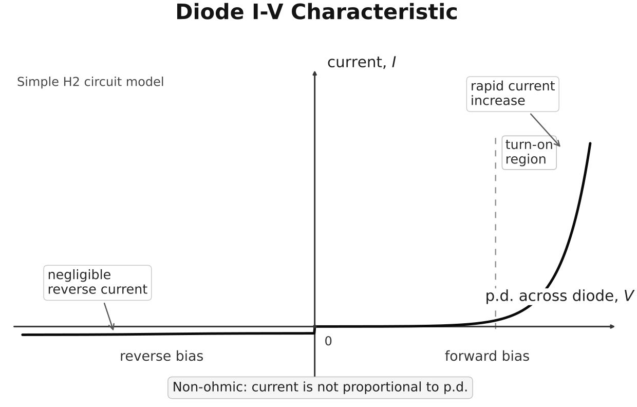
Figure: Under the stated sign convention, reverse-bias current is negligible in the simple model, whereas forward current rises steeply after the turn-on region. The curve is asymmetric and is not a straight line through the origin.
The graph shows that the diode is non-ohmic. For an ohmic component at constant temperature,
so its – graph is a straight line through the origin. The diode curve is neither linear nor symmetric.
Resistance at an operating point
The definition
can still be used at one operating point where . However, the value changes as the operating point changes. Therefore, do not treat the diode as a resistor with one constant .
6. NTC thermistor characteristics
An NTC thermistor is a temperature-sensitive resistor with a negative temperature coefficient over its working range:
“Negative” describes the slope of the –temperature graph, not the resistance itself. The thermistor’s resistance remains positive:
Current–voltage characteristic
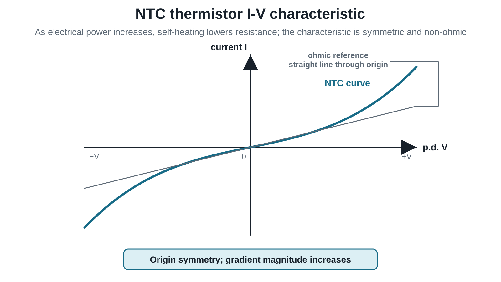
Figure: The NTC thermistor I–V characteristic passes through the origin and is symmetric under polarity reversal. Its increasing gradient in magnitude shows that decreases as self-heating raises the thermistor’s temperature. It is therefore non-ohmic.
As the magnitude of the applied p.d. increases, current and heating power increase. The thermistor becomes hotter, its resistance falls, and the magnitude of current rises more rapidly than it would for a constant-resistance component. Reversing the polarity reverses but does not change the heating mechanism, giving origin symmetry for an ordinary non-polar thermistor.
This explanation assumes the characteristic is measured under conditions where self-heating is significant. At a fixed controlled temperature and sufficiently small measuring current, the device may behave approximately ohmically over a limited range.
Resistance–temperature characteristic
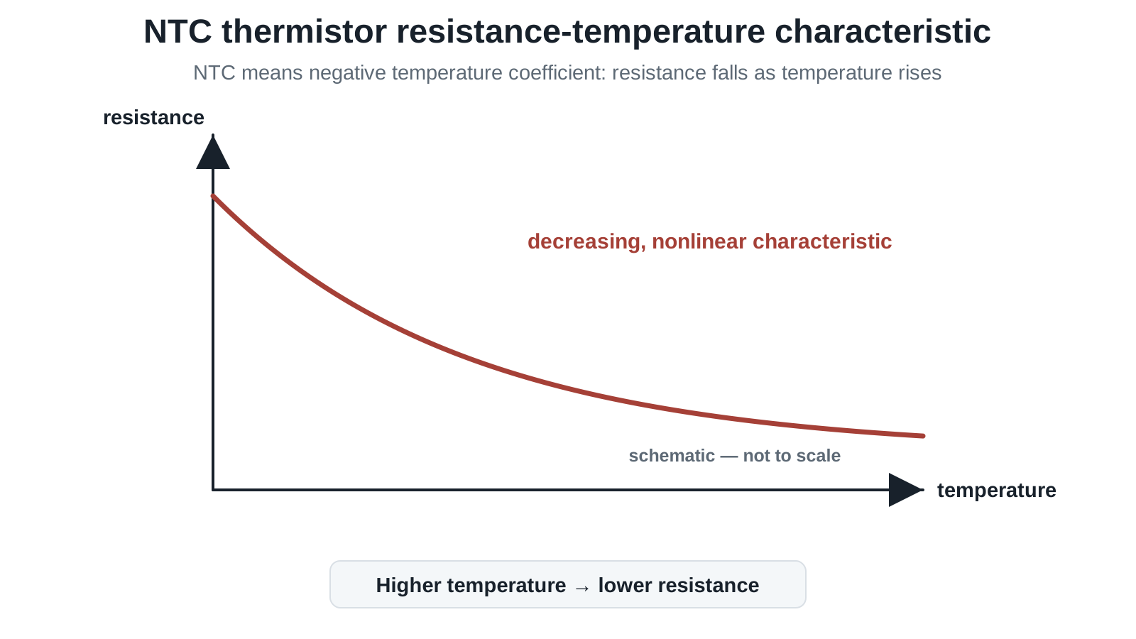
Figure: The required –temperature characteristic slopes downward and is generally non-linear. The negative gradient means ; it does not mean that is negative. The graph shows a qualitative trend, not a universal calibration curve.
Heating a metal usually increases its resistance because enhanced lattice vibration increases scattering. In an NTC semiconductor, the increase in mobile-carrier availability dominates over the additional scattering, so resistance falls.
See Thermistors and LDRs for potential-divider applications.
7. LDR trend
For a light-dependent resistor,
Light provides energy that increases the availability of mobile carriers. The syllabus requires the qualitative trend and its use in a potential divider; it does not require a universal algebraic –illumination law.
8. Diode models used in circuit questions
Ideal-diode model
- forward biased: closed switch with negligible p.d.;
- reverse biased: open switch with zero current.
Constant-drop model
- forward current is allowed only when the stated turn-on condition is met;
- the conducting diode has the stated approximate p.d. across it.
Do not mix the two models within one calculation.
9. Core application: half-wave rectification
A single diode in series with a load can pass one source half-cycle and block the other. The load current therefore keeps one direction but varies with time. The result is pulsating DC, not steady DC.
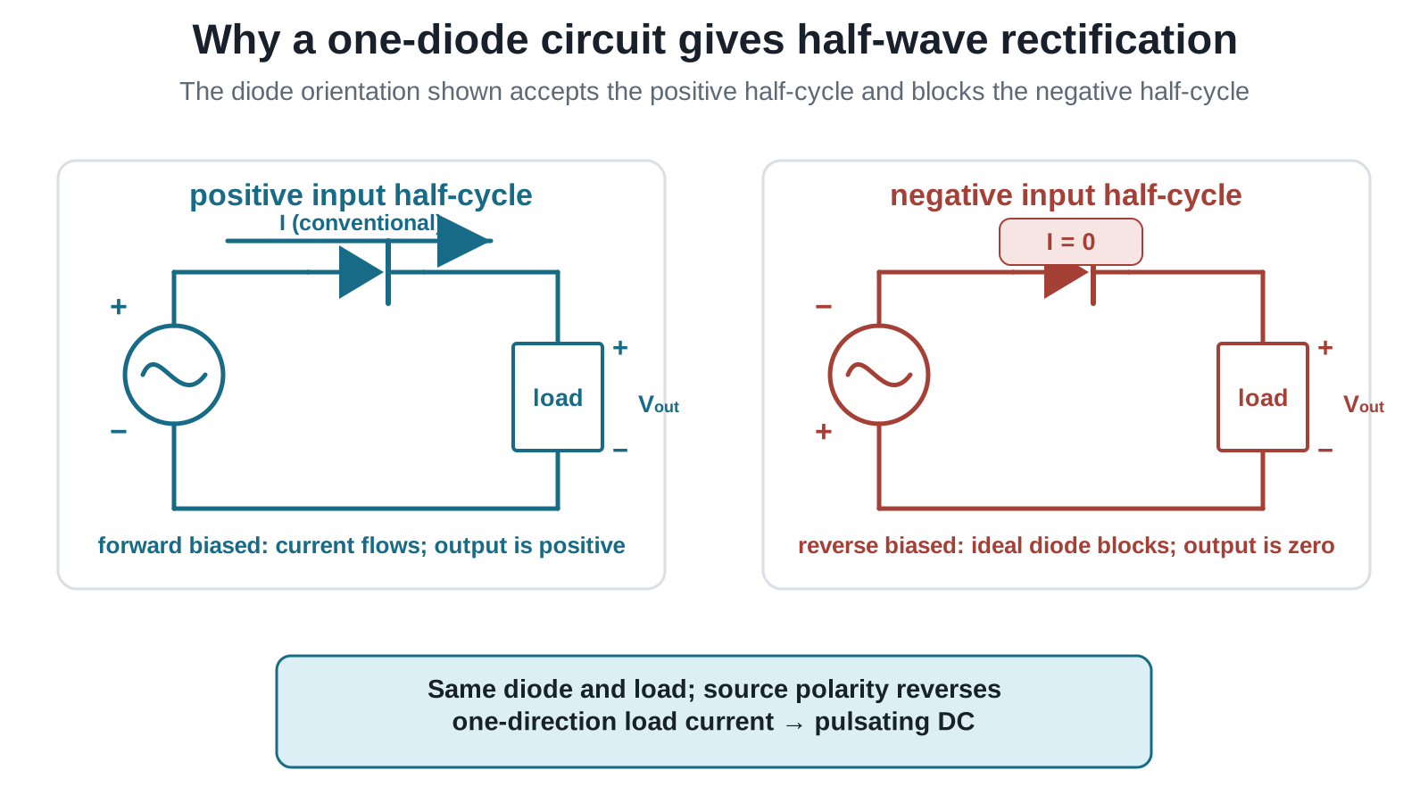
Figure: In the conducting state, the displayed source polarity forward biases the diode and conventional current passes through the load, producing the marked positive . When the source polarity reverses, the diode is reverse biased, the ideal current is zero, and for the same output reference.
See Rectification for the complete core explanation.
10. Enrichment
Bridge rectification and smoothing
A four-diode bridge can use both input half-cycles while preserving one load-current direction. A capacitor across the load can reduce output ripple. These are useful extensions, but outcome 18(f) explicitly requires only a single diode for half-wave rectification.
LEDs
A light-emitting diode emits light when forward current flows. The microscopic emission mechanism and LED material design are beyond the required scope.
11. Worked reasoning examples
Example 1: identify a diode region
A graph shows negligible current for and rapidly increasing current for sufficiently positive .
- The negative-p.d. side is reverse bias under the stated convention.
- The positive-p.d. side is forward bias.
- The component is non-ohmic because is not proportional to .
Example 2: compare metal and NTC behaviour
When temperature rises:
- a metal wire normally has greater resistance;
- an NTC thermistor has smaller resistance over its operating range.
The opposite trends arise because different microscopic effects dominate; “all hot components have greater resistance” is false.
Example 3: model choice
An ideal forward-biased diode in series with a resistor is connected to a supply. The model gives
If instead the question specifies a diode drop,
The different answers result from different stated models.
12. Common mistakes
- calling a hole a moving proton;
- confusing the NTC – graph with its –temperature graph;
- drawing the NTC I–V characteristic as polarity-asymmetric like a diode;
- calling the diode ohmic because can be evaluated at one point;
- assuming the silicon turn-on p.d. is an exact universal constant;
- inventing reverse breakdown when it is not supplied;
- deciding a sensor-divider output trend without locating the output terminals;
- calling unsmoothed rectified output steady DC;
- treating bridge rectification or LED theory as required core.
Exam Relevance
For an I–V graph, name the axes and sign convention. Explain the diode’s polarity-asymmetric conduction, but the NTC thermistor’s origin-symmetric, progressively steeper characteristic caused by self-heating. For the NTC –temperature graph, sketch resistance falling non-linearly as temperature rises. For sensor circuits, first state the resistance trend, then apply the potential-divider equation. For rectification, trace conventional current separately for the two source polarities.
Links
- Thermistors and LDRs
- Rectification
- Current Electricity Fundamentals
- Potential Divider
- Alternating Current
Summary
The required observable relationships are:
A single diode passes one AC half-cycle and blocks the other, producing unidirectional but time-varying output.