Alternating Current
Overview
An alternating current (AC) is a current whose direction reverses periodically. Its instantaneous value may be positive or negative: the sign records the chosen direction, not a different kind of current. A sinusoidal current also changes continuously in magnitude, but alternating waveforms need not all be sinusoidal.
This repository calls the unit Topic 19; it corresponds to Topic 18: Alternating Current in the 2026 H2 Physics 9749 syllabus. The examinable core is:
- waveform quantities and the equation
- peak and rms current or voltage
- mean power in a resistive load
- the ideal iron-core transformer
- single-diode half-wave rectification
Full-wave rectification, smoothing, detailed transformer losses and grid transmission are retained below only as enrichment.
Core Ideas
- AC reverses direction; DC remains in one direction.
- A negative value on a graph means the current or voltage has the opposite reference direction or polarity.
- The mean of a symmetric sinusoidal current is zero, yet it transfers energy because heating depends on .
- The rms value is the effective value for heating and resistive-power calculations.
- A transformer needs changing magnetic flux, so it operates with AC rather than steady DC.
- A diode can allow one half-cycle to reach a load and block the other.
AC, steady DC and pulsating DC
The labels describe direction as well as time variation:
| Signal | Direction | Magnitude | Example |
|---|---|---|---|
| steady DC | one direction | constant | ideal cell supplying a fixed resistor |
| varying or pulsating DC | one direction | changes with time | unsmoothed rectifier output |
| AC | reverses periodically | may change continuously or in steps | sinusoidal mains supply; square-wave AC |
Therefore, DC does not necessarily mean constant, and AC does not necessarily mean sinusoidal. A frequency is normally assigned to a repeating signal; steady DC is simply constant in time.
Reading a sinusoidal waveform
For a sinusoidal alternating quantity,
where may represent current or voltage, is the peak magnitude and fixes the phase at . When the graph crosses zero in the positive direction at , and the syllabus form is
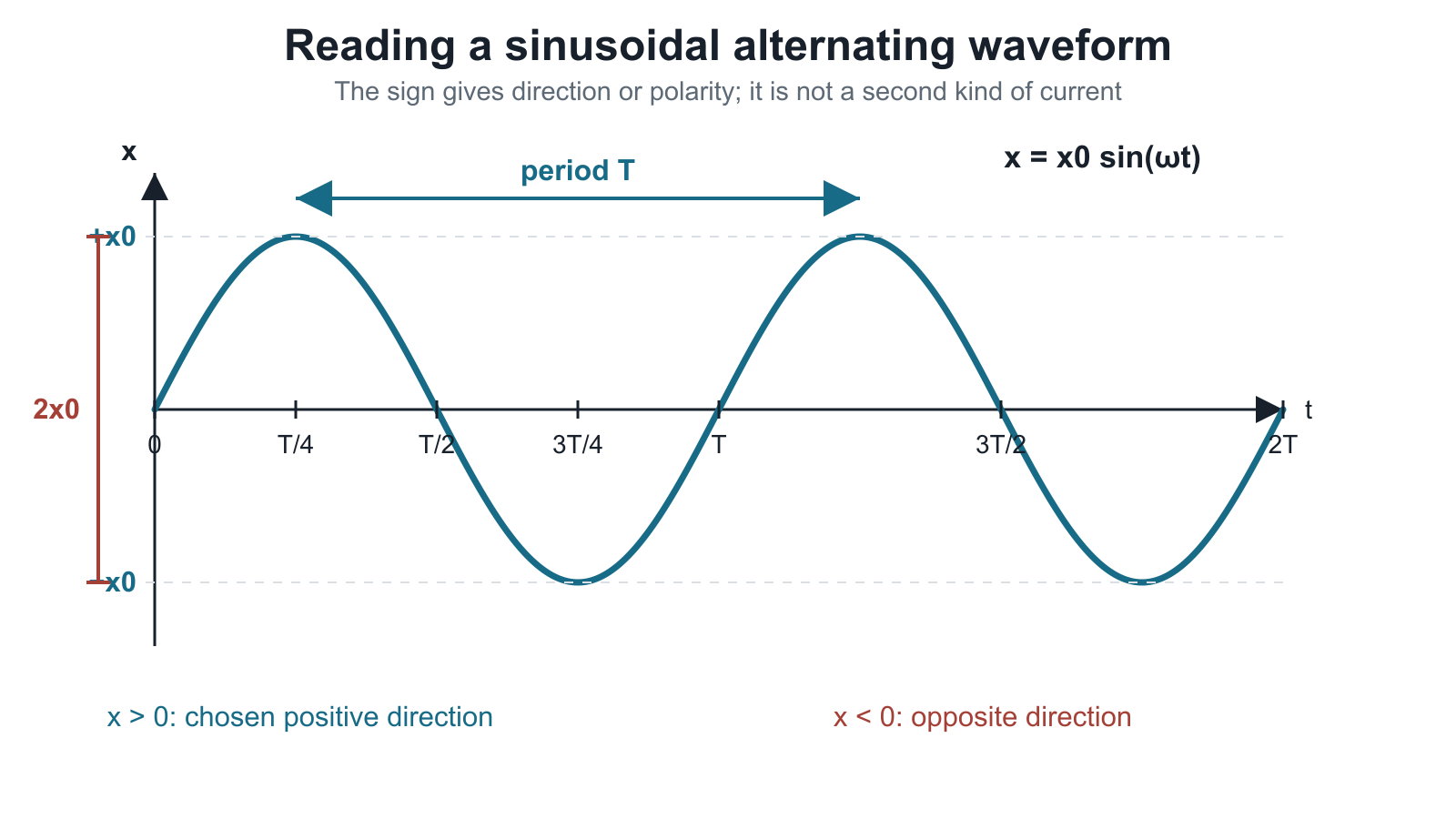
Figure: An analytical sine wave. The peak value is measured from the zero line, the peak-to-peak value is , and the period is the horizontal separation between equivalent points such as successive positive peaks. The sign of specifies direction or polarity.
The waveform quantities are:
- instantaneous value : value at one stated time
- peak value : maximum magnitude
- peak-to-peak value: for a symmetric sinusoid
- period : time for one complete cycle, in seconds
- frequency : number of complete cycles per second, in hertz
- angular frequency : rate of phase change, in radians per second
Worked waveform example
Suppose
Comparison with gives
Hence
At , . Its sinusoidal rms value is .
Mean and rms values
Over a complete cycle, the positive and negative parts of a symmetric sinusoidal current cancel, so its mean current is zero. This does not mean zero heating: in a resistor,
which is non-negative for either current direction.
The rms current is the value of steady DC that gives the same mean heating power in the same resistor:
For a sinusoidal waveform only,
See RMS and AC Power for the derivation and a non-sinusoidal example.
Power in a resistive load
For a pure resistor, current and voltage are in phase. If
then
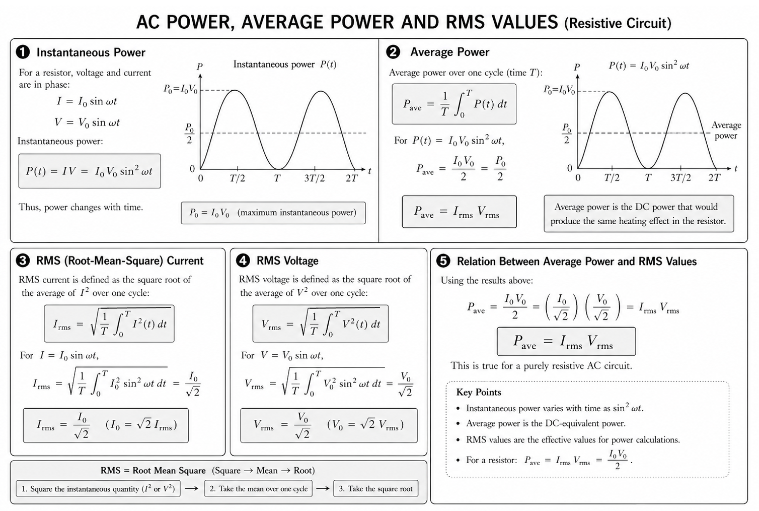
Figure: Current reverses every half-cycle, but never becomes negative. The maximum instantaneous power is . Since the cycle mean of is , . The power waveform repeats every .
Thus, for a sinusoidal current in a resistor,
Using rms quantities gives the familiar resistive-load relations
The product equals mean power here because a pure resistor makes and in phase. Do not apply that statement automatically to arbitrary AC components.
Ideal iron-core transformer
A transformer contains primary and secondary coils wound on a common iron core.
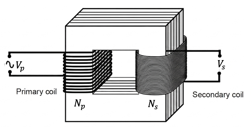
Figure: AC in the primary produces changing magnetic flux in the core. The changing flux links the secondary turns and induces an alternating emf. In the ideal model, all flux links both coils and no energy is lost.
The causal sequence is
For an ideal transformer,
where voltages and currents are rms values. Also,
- If , the transformer is step-up: voltage rises and current falls.
- If , it is step-down: voltage falls and current rises.
The instantaneous polarity of one winding relative to the other depends on winding sense and reference terminals; do not assert a universal phase difference without this information.
Worked transformer example
An ideal transformer has , , and rms. Then
If the secondary current is ,
Single-diode half-wave rectification
A diode conducts conventional current readily in its forward direction and blocks it in the reverse direction.
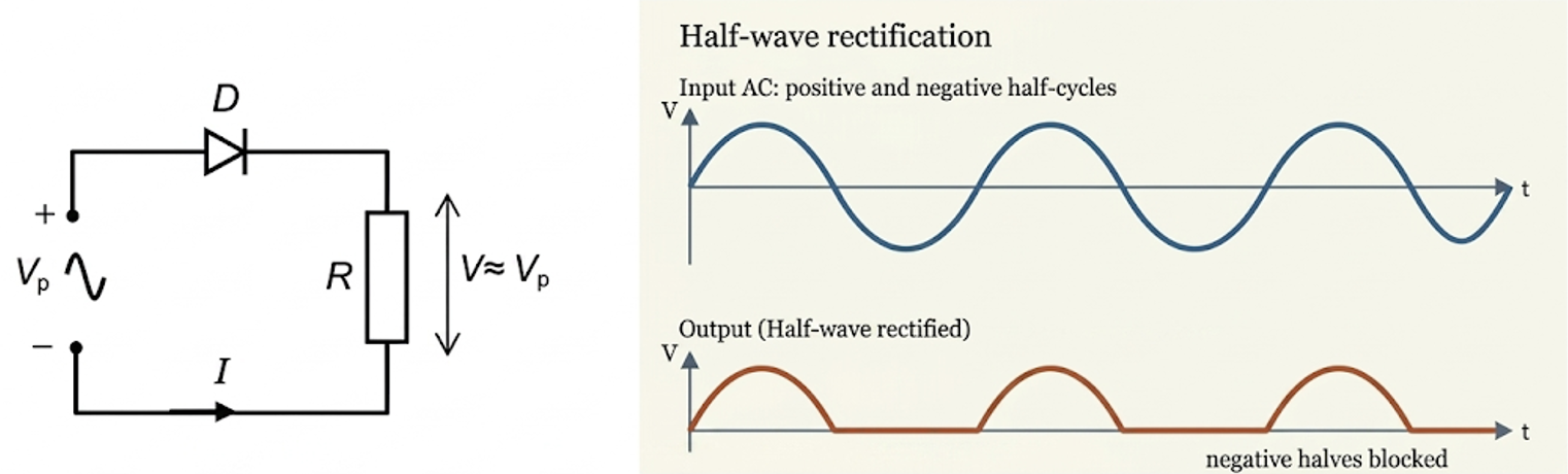
Figure: During the positive input half-cycle, the diode is forward-biased and current passes through the load; the return current flows back toward the source. During the negative half-cycle, the diode is reverse-biased, so an ideal diode gives zero load current. The output retains one polarity but varies with time: it is pulsating DC.
For the ideal circuit shown,
A real conducting diode has a small forward voltage drop, but the ideal-diode approximation is normally used unless data are supplied.
Enrichment beyond the stated Topic 18 core
Full-wave rectification and smoothing
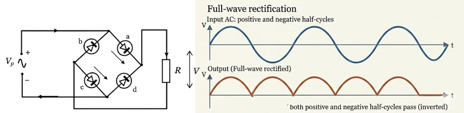
Figure: Enrichment bridge-rectifier model. Both input half-cycles are redirected so that load current has one direction. For an ideal sinusoidal input, the unsmoothed output is proportional to and its pulse frequency is . A smoothing capacitor can reduce, but not normally eliminate, ripple.
The detailed semiconductor treatment is in Rectification.
High-voltage transmission
For fixed real power transmitted in the simplified in-phase model,
Raising the transmission voltage lowers the cable current and therefore lowers heating loss strongly.
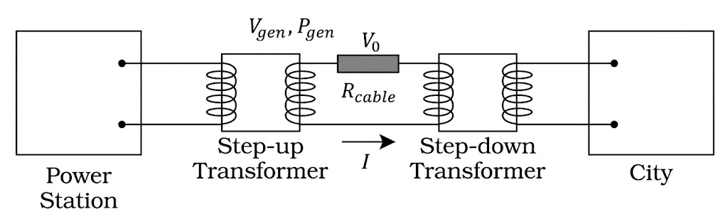
Figure: Enrichment transmission model. At the same delivered power, multiplying transmission voltage by divides current by and cable loss by , assuming the same cable resistance and the simplified in-phase model.
Detailed transformer losses and efficiency are treated in Transformers.
Exam Relevance
Before calculating, identify whether each value is instantaneous, peak, peak-to-peak or rms. State waveform-specific assumptions, especially “sinusoidal”, “pure resistor” and “ideal transformer”. In rectification questions, trace the allowed conventional-current path rather than memorising an arrow.
Links
- RMS and AC Power
- Alternating Current Common Exam Traps
- Electromagnetic Induction
- Transformers
- Rectification
Summary
For sinusoidal AC,
For a pure resistor,
An ideal transformer obeys
and a single diode produces a unidirectional, pulsating half-wave output.