Magnetic Fields
Where this dossier sits in the syllabus
The official 9749 syllabus places field production and magnetic force together under Electromagnetism. This repository separates them for learning: this dossier covers field sources, patterns, the three standard field expressions and the qualitative effect of a ferrous core. Forces on wires and charges, the operational definition of the tesla, current balance and velocity selection are developed in Magnetic Force.
Overview
This hub introduces magnetic-field representation, fields produced by permanent magnets and currents, and the formula domains for a straight wire, circular coil, and long solenoid.
Core Ideas
- Magnetic field diagrams are vector-field representations: tangent, arrow direction, and relative spacing matter.
- Conventional current determines the direction of current-produced magnetic fields.
- The three standard field expressions apply only to their stated geometries and observation regions.
- Ferrous cores strengthen solenoid fields qualitatively; they do not use the air-core formula without additional data.
Exam Relevance
Topic 16 questions usually test diagram interpretation, right-hand grip-rule direction, formula selection, unit conversion, and qualitative explanation of solenoids or ferrous cores.
1. What is a magnetic field?
A magnetic field is a field of force produced by permanent magnets or electric currents. At each point it is represented by the vector magnetic flux density .
The direction of at a point is the direction in which the north-seeking end of a very small compass would point. Its SI unit is the tesla, .
A bridge to Topic 17
Magnetic flux density can be defined operationally using the force on a current-carrying conductor. That definition and its force experiment belong to Magnetic Force. Here, the task is to interpret, compare and calculate fields produced by specified sources.
2. Reading a magnetic-field diagram
Field lines are a representation, not physical strings or electron paths.
- The tangent to a field line gives the local direction of .
- Arrowheads show the direction of .
- Closer spacing represents a larger within the same consistently drawn diagram. The number of lines drawn is otherwise arbitrary.
- Magnetic field lines form closed loops. Around a bar magnet they run from N to S outside the magnet and return from S to N inside it.
- Field lines do not cross at a point where , because the field cannot have two directions at one point.
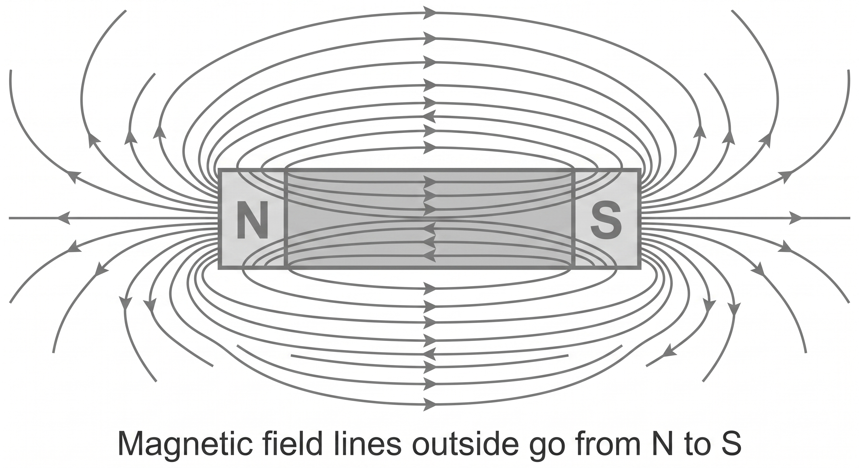
Figure: A bar magnet field is represented by complete closed loops. Outside the magnet, field lines run from N to S; inside the magnet, the return part of each loop runs from S to N.
Into and out of the page
- means a vector points out of the page, like the tip of an approaching arrow.
- means a vector points into the page, like the feathers or tail of a departing arrow.
These symbols can represent current, field, velocity or another vector. Read the nearby label; they are not positive and negative charges.
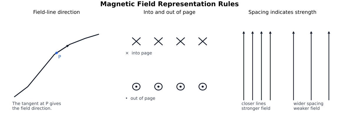
Figure: Dot and cross symbols show arrow tip and arrow tail directions, not positive and negative charges. Uniform fields are drawn with parallel equally spaced lines; closer spacing indicates stronger field only within one consistently drawn diagram.
“Flux pattern” is not magnetic flux
In this section, a magnetic flux pattern means the pattern of field lines. The scalar magnetic flux through an area is a different quantity introduced in Electromagnetic Induction.
3. Two right-hand grip rules
Both rules use conventional current, not electron drift.
Straight wire
Point your right thumb in the direction of conventional current. Your curled fingers give the circular direction of .
- current out of the page field anticlockwise;
- current into the page field clockwise.
Coil or solenoid
Curl your right-hand fingers in the direction of conventional current around the turns. Your thumb gives the field direction through the coil or inside the solenoid and points towards its north pole.
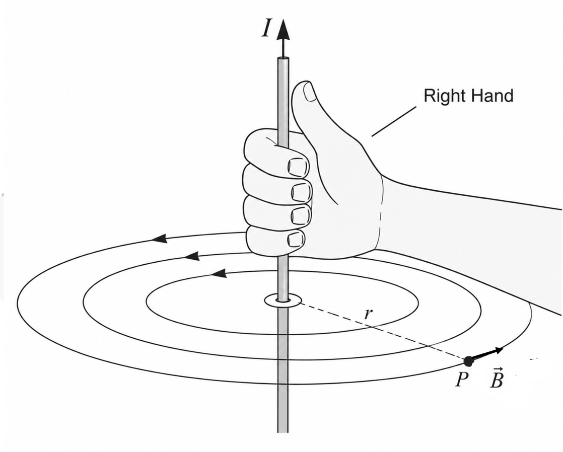
Figure: The right-hand grip rule uses conventional current. For a straight wire, the thumb gives current and curled fingers give ; for a coil or solenoid, curled fingers follow current and the thumb gives the axial field and north-pole direction.
4. The three required field geometries
The permeability of free space is
4.1 Long straight wire
Outside a long straight wire in air or free space, at perpendicular distance from the wire and sufficiently far from its ends,
The formula gives magnitude. Use the straight-wire grip rule for direction. Doubling doubles at the same ; doubling halves at the same .
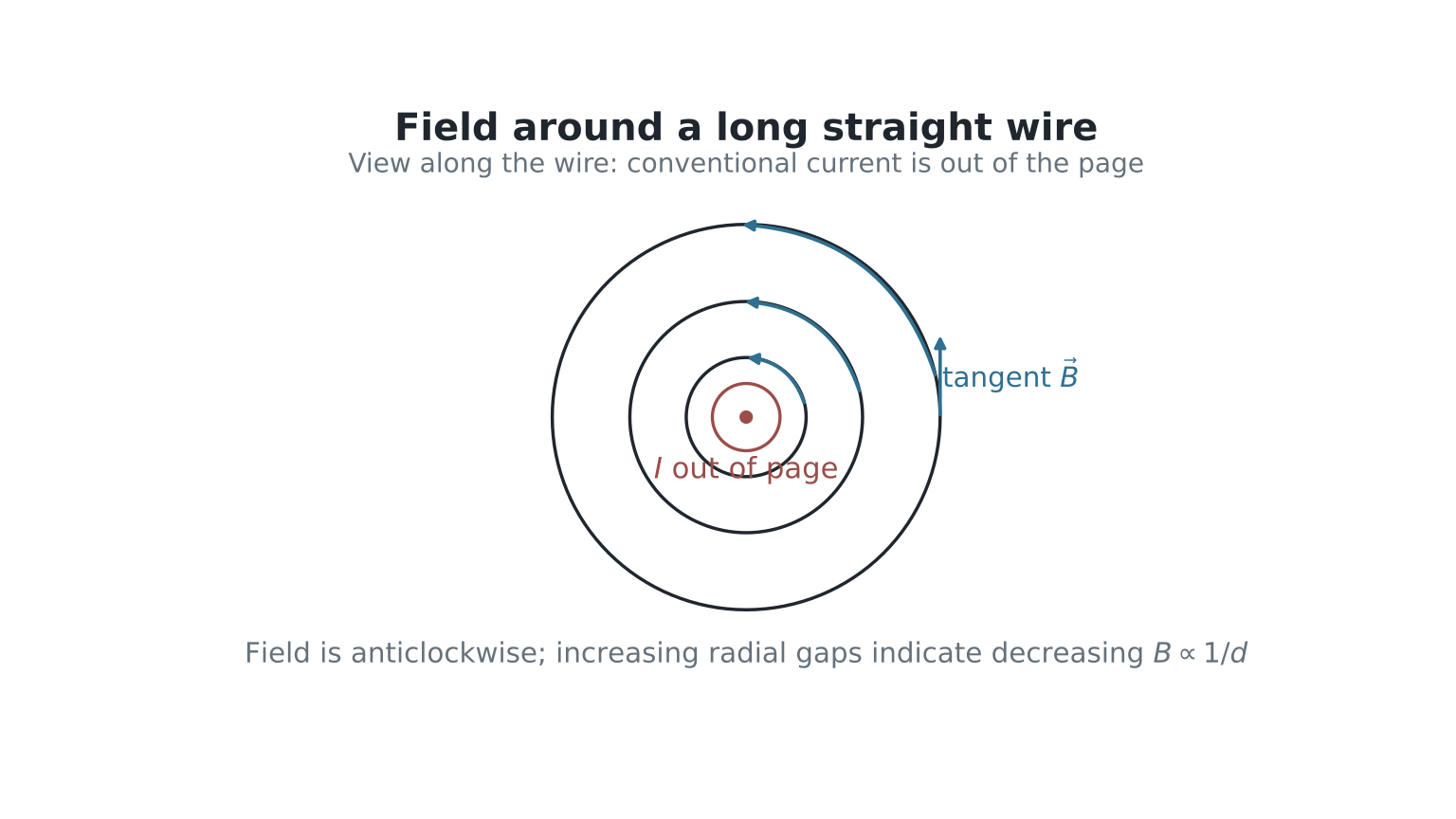
Figure: Around a long straight wire, magnetic field lines are concentric circles centred on the wire. For current out of the page, the field is anticlockwise as seen by the reader; at any point is tangent to the circle.
4.2 Flat circular coil
At the centre of closely coincident turns of common radius in air or free space,
The central field is perpendicular to the coil plane. Contributions from the turns reinforce there. This statement does not mean that the centre is the point of greatest field everywhere around an ideal thin conductor.
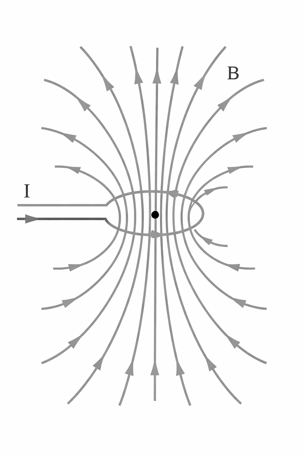
Figure: A current-carrying circular coil produces an axial field through the centre. The face-on view fixes the current rotation and centre-field direction; the side view reminds students that the complete field pattern closes like a bar-magnet field.
4.3 Long solenoid
For the central region of a long, closely wound air-core solenoid, away from end effects,
where is the number of turns per unit length in , is the total number of turns and is the solenoid length.
The field is approximately uniform inside the central region and much weaker outside a long solenoid. It is not exactly zero outside a finite solenoid.
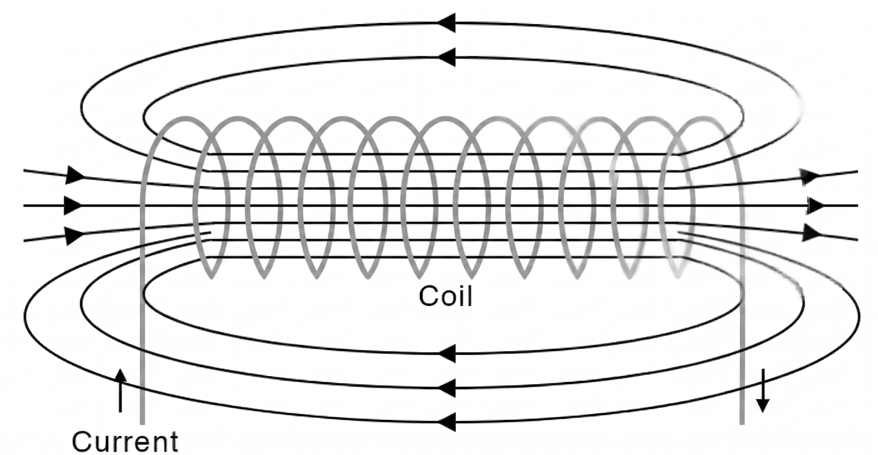
Figure: A long solenoid has a strong, nearly uniform central field and a weaker external return field. The internal field direction points from the solenoid’s south end towards its north end.
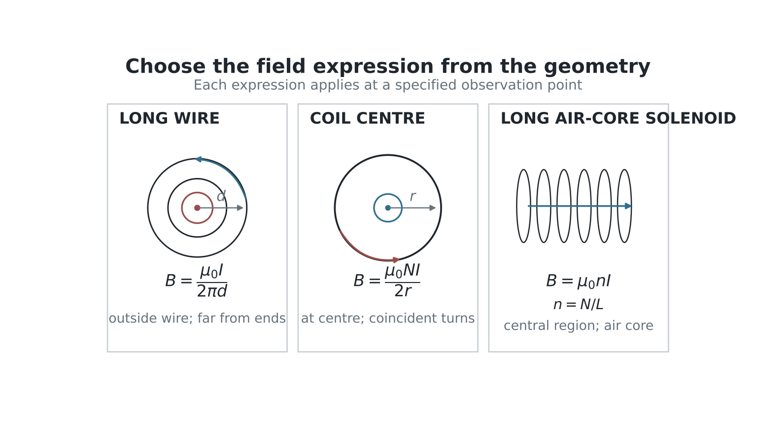
Figure: The three standard field expressions apply to different geometries and locations: distance from a long straight wire, centre of a circular coil of radius , and central region of a long air-core solenoid with turn density .
5. Ferrous core: what changes?
Inserting a soft-ferrous core magnetises the material. Its magnetisation contributes to the field and concentrates the field through the core, so is larger for the same current and turn density.
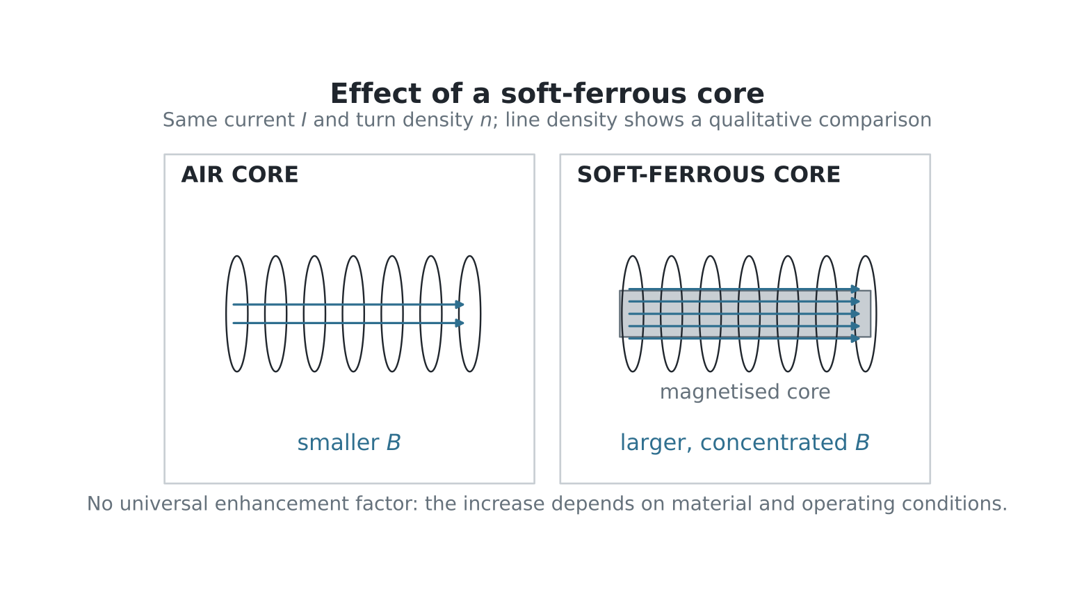
Figure: A soft ferrous core becomes magnetised and concentrates the field through the solenoid. The field is stronger for the same current and turn density, but the increase is qualitative and material-dependent, not a universal multiplier in .
Formula limit
is the ideal air-core expression. Do not use it unchanged to calculate the field of a ferrous-core solenoid unless the question supplies an appropriate material model or data. The enhancement is material-dependent and has no universal multiplication factor.
An electromagnet is a device whose field is produced by current. It commonly uses a coil or solenoid with a soft-ferrous core for a stronger, controllable field, but current in an air-core solenoid already produces magnetism.
6. Worked examples
Example 1: long wire
A long wire carries . Find at a point from it.
If the current is out of the page, the field is anticlockwise; the direction at the chosen point is tangent to its circular field line.
Example 2: circular coil
A 20-turn coil of radius carries .
The value is specifically the field at the centre. The direction follows from the coil grip rule.
Example 3: solenoid
A air-core solenoid has 800 turns and carries .
Reversing the current reverses the field and swaps the poles, but does not change this magnitude if is unchanged.
7. Enrichment: useful model extensions
The following ideas are useful but are not core recall equations for outcomes (a)–(d):
- vector unit directions such as for a wire field;
- detailed domain, permeability and hysteresis models;
- engineering details of relays, lifting magnets and magnetic circuits;
- the ideal long-solenoid end approximation
which is not a general solenoid formula.
8. Checklist
Before finalising an answer, ask:
- Which geometry is present?
- Where is the field being evaluated?
- Are the formula assumptions satisfied?
- Did I convert centimetres to metres and calculate where needed?
- Did I give a direction using the correct version of the right-hand rule?
- If there is a ferrous core, have I avoided using the air-core formula without extra data?