Alternating Current Generators
Overview
An alternating current generator converts mechanical energy into electrical energy by electromagnetic induction.
A coil rotates in a magnetic field, causing the magnetic flux linkage through the coil to change continuously. By Faraday’s law, an alternating emf is induced.
This topic applies ideas from Electromagnetic Induction.
Core Ideas
AC-generator questions revolve around a small set of linked ideas:
- a rotating coil produces changing flux linkage
- changing flux linkage induces emf
- the output is alternating because the sign changes every half-turn
- flux linkage and emf are sinusoidal but phase shifted
- peak emf depends on , , , and
- output frequency is set by rotational frequency
Exam Relevance
Students are expected to:
- explain the function of slip rings and brushes
- connect rotating-coil diagrams to changing flux linkage
- interpret waveform phase relations correctly
- use and
- distinguish maximum flux linkage from maximum emf
Link to Electromagnetic Induction
The generator is a direct application of electromagnetic induction:
- rotating the coil changes the angle between coil normal and field
- flux linkage changes continuously
- changing flux linkage induces emf
See Electromagnetic Induction.
Key Representations
Basic Construction
A simple AC generator consists of:
- a rectangular coil of turns
- strong magnets producing magnetic field
- slip rings connected to the coil ends
- carbon brushes making external contact
- an axle or shaft connected to a turbine or motor
Functions of Components
Coil
Rotates through the magnetic field so flux linkage changes.
Magnets
Provide magnetic flux density .
Slip Rings
Rotate with the coil and maintain continuous electrical connection while allowing alternating output.
Brushes
Stationary contacts that collect current from the rotating slip rings.
Axle or Turbine
Supplies mechanical rotational energy.
Visual Reference
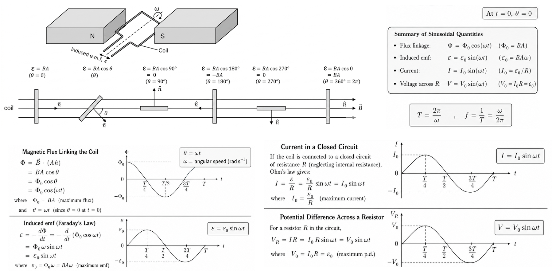
Figure: A rotating coil in a magnetic field connected to slip rings and brushes. As the coil turns, flux linkage changes and an alternating emf is produced.
Principle of Operation
When the coil rotates:
- the angle between coil normal and magnetic field changes
- magnetic flux linkage changes
- induced emf is produced
By Faraday’s law:
Because the flux linkage changes periodically, the emf also changes periodically and reverses direction every half-turn.
Hence the output is alternating current if the circuit is complete.
Flux-Linkage Model
If the coil rotates with angular speed :
where:
- = number of turns
- = magnetic flux density
- = area of coil
- = angular speed
This means flux linkage varies sinusoidally with time.
Induced-emf Model
Using Faraday’s law:
Thus the induced emf is also sinusoidal.
Waveform Overview
Sinusoidal emf
Output emf varies smoothly between positive and negative peak values.
Phase Relation with Flux Linkage
Since emf is the derivative of flux linkage:
- maximum flux linkage gives zero emf
- zero flux linkage gives maximum emf
So the two graphs are phase shifted by .
Sign Change Every Half-Turn
After each half rotation, sides of the coil move in opposite directions compared with before, so induced emf reverses sign.
For full graph reasoning, see AC Generator Waveforms.
Maximum emf
Peak emf:
This is the amplitude of the sinusoidal output.
Larger peak emf can be achieved using:
- larger
- larger
- larger
- faster rotation
Frequency of Output
The electrical frequency equals the rotational frequency of the coil.
where:
- = frequency
- = period
If the coil completes one revolution each second:
Energy Conversion
Input:
- mechanical rotational energy from a turbine, engine, or crank
Output:
- electrical energy in alternating form
Energy is not created; it is converted.
If electrical load increases, greater mechanical torque is required.
Factors Affecting Output
Magnitude of emf
Depends on:
So increase any of:
Frequency
Depends on rotational speed only.
Faster rotation gives higher frequency.
Why Slip Rings Are Used
Slip rings allow:
- continuous rotation of the coil
- continuous electrical contact
- output polarity to reverse naturally
Hence AC is produced.
Compare this with the split-ring commutator used in DC machines.
Power-Station Context
Large-scale generators use turbines driven by:
Steam Turbine
Steam from burning fuels or nuclear heating.
Hydroelectric Turbine
Moving water turns a turbine.
Wind Turbine
Wind rotates blades connected to a generator.
All use the same induction principle.
Worked Examples
Example 1: Peak emf
A generator has:
Example 2: Frequency
If period is:
Then:
Example 3: Instant of Maximum emf
Maximum emf occurs when flux linkage is zero.
Formula Sheet
Flux Linkage
Instantaneous emf
Peak emf
Frequency
Brief Common Mistakes
- thinking maximum flux gives maximum emf
- forgetting slip rings maintain AC output
- confusing period and frequency
- using as instantaneous emf
- forgetting phase shift between flux and emf
See Alternating Current Generators Common Exam Traps.