Electromagnetic Induction
Topic hub: This note develops the examinable chain from experimental observations to magnetic flux, Faraday’s law, Lenz’s law, graphs, and simple applications. Use the branch notes for detailed motional-emf reasoning and common exam traps.
Syllabus map: Repository Topic 18 corresponds to Topic 17 in the 2026 H2 Physics 9749 syllabus. Detailed alternating-current, generator-construction, and transformer-ratio work remains in the later topic notes.
Overview
Electromagnetic induction is the production of an emf when magnetic flux linkage changes. The topic connects experimental observations, magnetic flux, Faraday’s law, Lenz’s law, graph interpretation, motional emf and eddy currents.
Core Ideas
- Induced emf depends on the rate of change of magnetic flux linkage, not simply on the size of the magnetic field.
- Magnetic flux is when is measured from the area normal.
- Faraday’s law gives the magnitude and sign convention for induced emf.
- Lenz’s law gives the direction by requiring the induced effect to oppose the change causing it.
- Motional emf can be explained either by charge separation in a moving conductor or by changing flux in a closed circuit.
- Eddy currents are induced current loops in bulk conductors and can be useful or wasteful.
Exam Relevance
Students are expected to apply magnetic-flux definitions with the correct angle, use Faraday’s law in average and graphical forms, apply Lenz’s law without guessing, explain motional emf conditions, and distinguish induced emf from induced current.
1. The central idea
For a circuit, an induced electromotive force (emf) is produced when its magnetic flux linkage changes. An open moving conductor can also develop a motional emf because the magnetic force separates charge along it.
- An emf can exist across an open circuit.
- An induced current flows only if there is a closed conducting path.
- A magnetic field may be large while the induced emf is zero: what matters is the rate of change of flux linkage, not flux linkage alone.
This distinction is the foundation of the topic.
2. What the experiments show
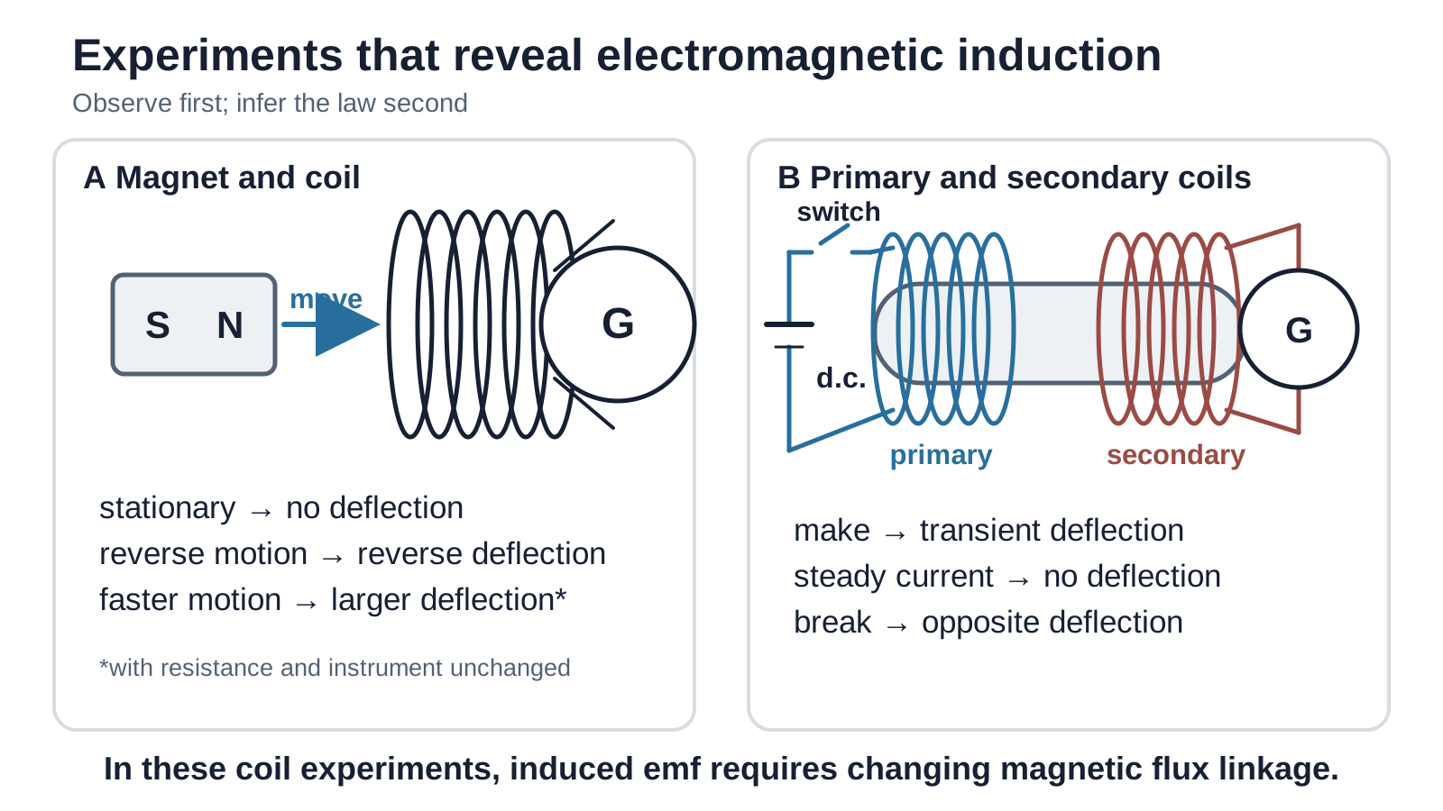
Figure: Experimental evidence for induction. A galvanometer measures current, so comparisons of its deflection imply comparisons of emf only when the circuit resistance and instrument remain unchanged. In the two-coil experiment, make and break cause opposite transient deflections; steady direct current produces no continuing deflection.
| Controlled observation | Inference |
|---|---|
| A magnet held stationary relative to a coil gives no deflection. | Non-zero magnetic flux alone does not cause induction. |
| Relative motion produces a momentary deflection. | Changing flux linkage can induce an emf. |
| Reversing the motion or the magnet pole reverses the deflection. | The induced emf has a direction related to the direction of change. |
| Faster motion gives a larger deflection, with resistance unchanged. | A greater rate of change of flux linkage gives a larger emf. |
| A stronger magnet gives a larger deflection when the circuit resistance and instrument are unchanged. | A larger change in flux per turn gives a larger emf and, under the controlled conditions, a larger current. |
| More turns give a larger emf for the same rate of change of flux per turn. | Flux linkage is the sum over linked turns. A raw deflection comparison also requires total circuit resistance to be controlled, because extra wire can increase resistance. |
| Switching current on and off in a nearby primary coil gives opposite momentary deflections in a secondary coil; steady current gives none. | A changing magnetic field can induce an emf; a constant field does not. |
The experiments support both Faraday’s law (magnitude) and Lenz’s law (direction).
3. Magnetic flux
3.1 Definition
For a flat area in a uniform magnetic field, magnetic flux is the product of the area and the component of magnetic flux density perpendicular to that area:
where is the angle between and a chosen area normal, a line perpendicular to the surface.
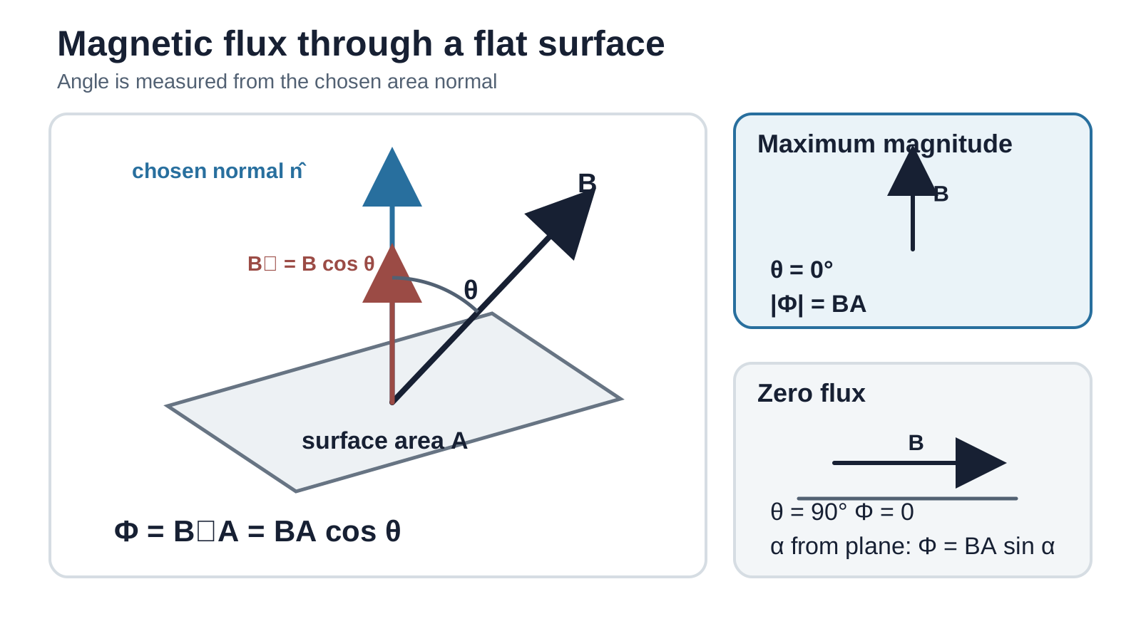
Figure: The safest convention measures from the area normal, giving . If a question gives the complementary angle between the field and the plane, use . Field lines are a visual representation; flux is not literally a count of lines.
3.2 Angle checks
- Field perpendicular to the plane: , so .
- Field parallel to the plane: , so .
- If the angle is measured from the plane, then and
3.3 Sign and unit
After choosing one normal as positive, flux in that normal direction is positive and flux in the opposite direction is negative. Reversing the chosen normal reverses the signs of both flux and the associated positive loop direction; physical predictions do not change if the convention is used consistently.
The SI unit is the weber (Wb):
Worked example 1: angle convention
A coil of area is in a uniform field of . The field makes with the plane of the coil.
The angle to the normal is , so
Equivalently, .
4. Magnetic flux linkage
For a coil of identical turns, each linking the same flux , the magnetic flux linkage is
Flux linkage can therefore change because , the linked area , or the orientation changes. Relative motion can also change how much of the circuit is within a field.
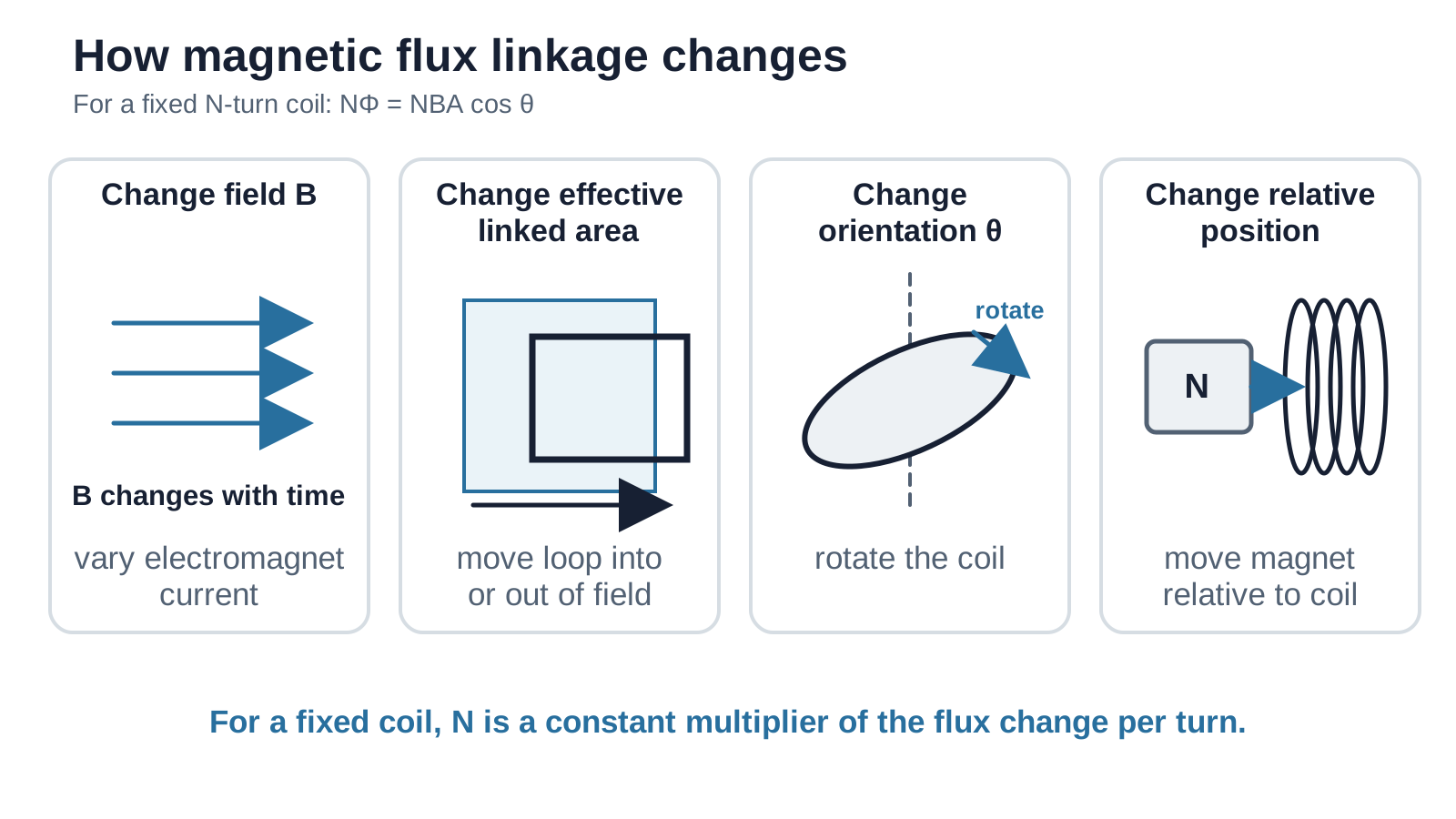
Figure: Common ways of changing flux linkage. A coil translating wholly inside a uniform field without changing its area or orientation has constant flux linkage and therefore no induced emf.
Important: Larger , , or can make a given change in flux linkage larger, but constant values do not themselves produce an emf.
Enrichment — beyond the required 9749 formula: For a non-uniform field, magnetic flux is defined by the surface integral . The uniform-field expression above is the form required for ordinary H2 calculations.
5. Faraday’s law
Faraday’s law states that the induced emf equals the negative rate of change of magnetic flux linkage:
For a change over a finite time interval,
When only the magnitude is required,
The minus sign does not mean that the magnitude of emf is negative. It records the direction required by Lenz’s law after a positive flux and positive circuit direction have been chosen.
Worked example 2: average induced emf
A 200-turn coil has flux per turn decreasing uniformly from to zero in .
Hence
Its direction cannot be found from the magnitude calculation alone; the diagram and chosen sign convention are also needed.
6. Lenz’s law and direction
Lenz’s law states:
The direction of an induced emf, and of the induced current if the circuit is closed, is such that its magnetic effect opposes the change in magnetic flux linkage that produces it.
The induced field does not always oppose the external field. It opposes the change:
- if external flux into the page is increasing, the induced field is out of the page;
- if external flux into the page is decreasing, the induced field is into the page, attempting to maintain it.
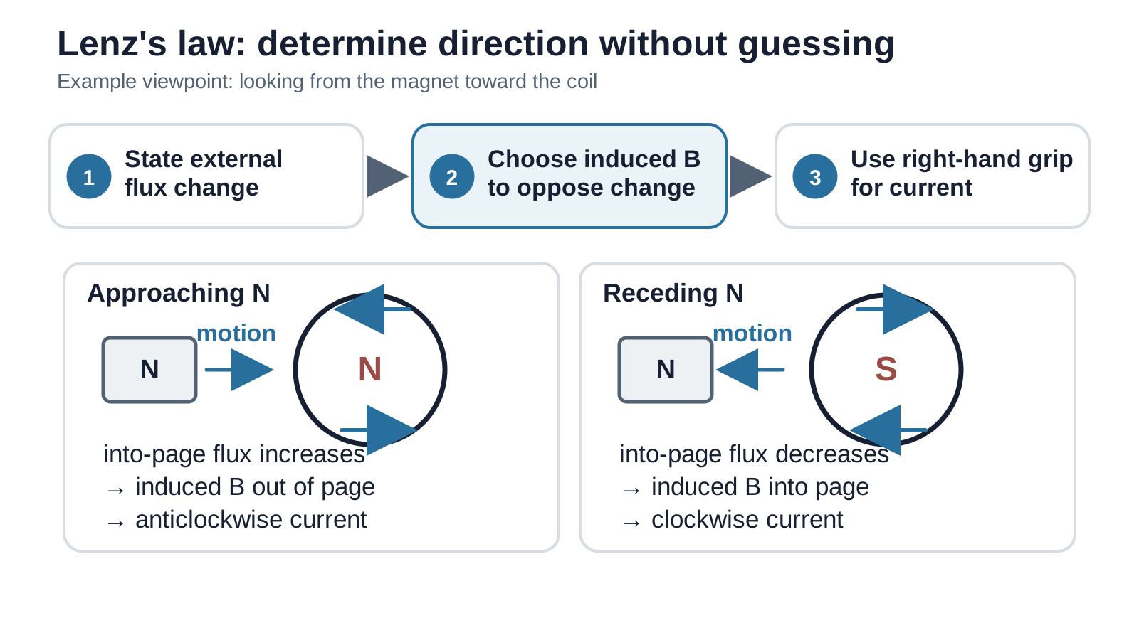
Figure: A reliable Lenz-law workflow. First state how the external flux changes; next choose the induced field that opposes that change; only then use the right-hand grip rule to obtain the conventional-current direction.
Why opposition is necessary
When a magnet approaches a closed coil, the induced current produces a force opposing the approach. External work is therefore required. That mechanical energy becomes electrical energy and eventually thermal energy in the circuit. If the induced effect reinforced the change without an external energy input, energy would be created, contradicting conservation of energy.
Worked example 3: direction chain
A north pole approaches a coil along its axis.
- Flux due to the magnet through the coil is increasing.
- The coil produces a field opposing this increase.
- The near face of the coil must therefore behave as a north pole and repel the magnet.
- Viewed from the magnet side, the induced conventional current is anticlockwise by the right-hand grip rule.
Do not jump directly from “magnet approaches” to a memorised clockwise or anticlockwise answer; the viewing side and pole matter.
7. Reading flux-linkage and emf graphs
From Faraday’s law, the signed emf at any instant is the negative gradient of the flux-linkage–time graph.
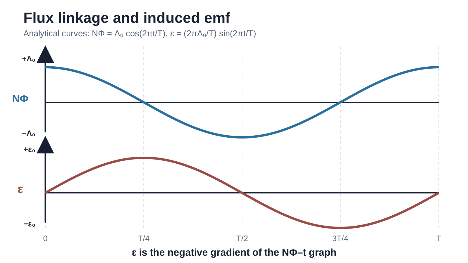
Figure: For , analytical differentiation gives . Emf is zero at flux-linkage maxima and minima, and its magnitude is greatest when flux linkage crosses zero most steeply.
For any graph:
- horizontal graph ;
- steeper graph larger ;
- positive gradient negative emf under the chosen convention;
- negative gradient positive emf.
Worked example 4: piecewise graph
Suppose flux linkage rises linearly from to during , remains constant for , then falls linearly to zero during .
The final pulse is three times larger because the same linkage change occurs in one-third of the time.
8. Motional emf
When a conductor moves through a magnetic field, its mobile charges experience the magnetic force . Charge separation can establish a potential difference across an isolated rod.
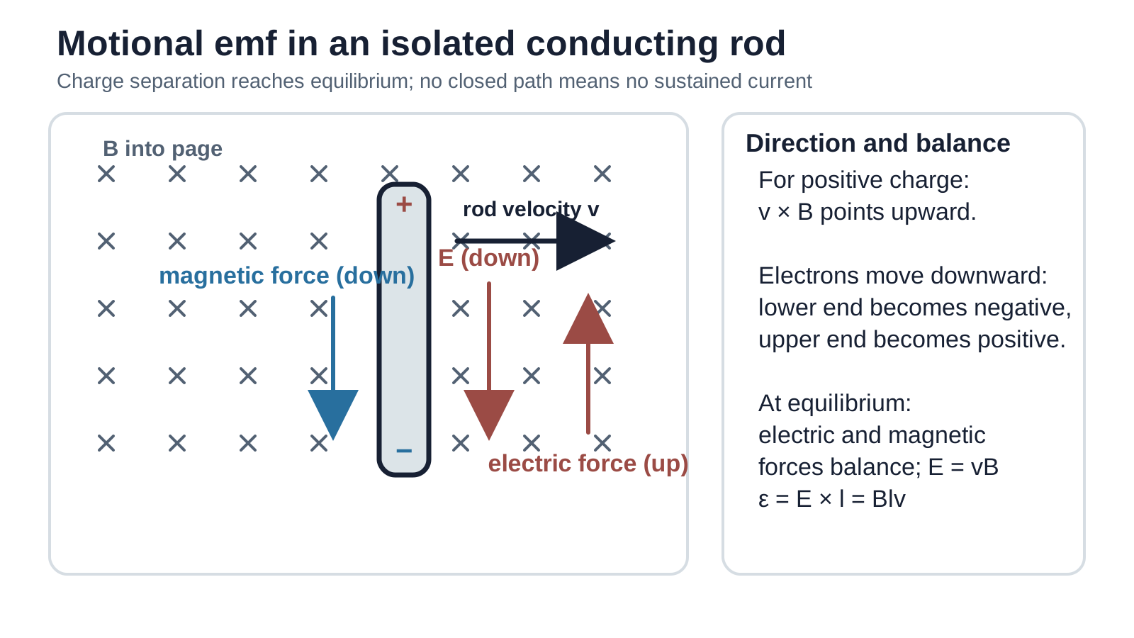
Figure: In an isolated rod moving right through a field into the page, points upward for positive charge. Electrons accumulate at the lower end, making the upper end positive. The resulting electric force eventually balances the magnetic force; an emf exists, but there is no sustained current without a closed circuit.
For the standard mutually perpendicular geometry,
The full assumptions and energy analysis are developed in Motional emf.
9. Simple applications
9.1 AC generator principle
Rotating a coil changes its orientation and hence its flux linkage. Faraday’s law therefore gives an alternating emf. Detailed generator construction and output are covered in Alternating Current Generators.
9.2 Transformer principle
Alternating current in a primary coil produces changing magnetic flux in a shared core. The changing flux links the secondary coil and induces an emf. A steady direct current does not produce a continuous secondary emf. Turns ratios and losses belong to Transformers.
9.3 Eddy currents
Changing flux through a bulk conductor induces closed current loops called eddy currents.
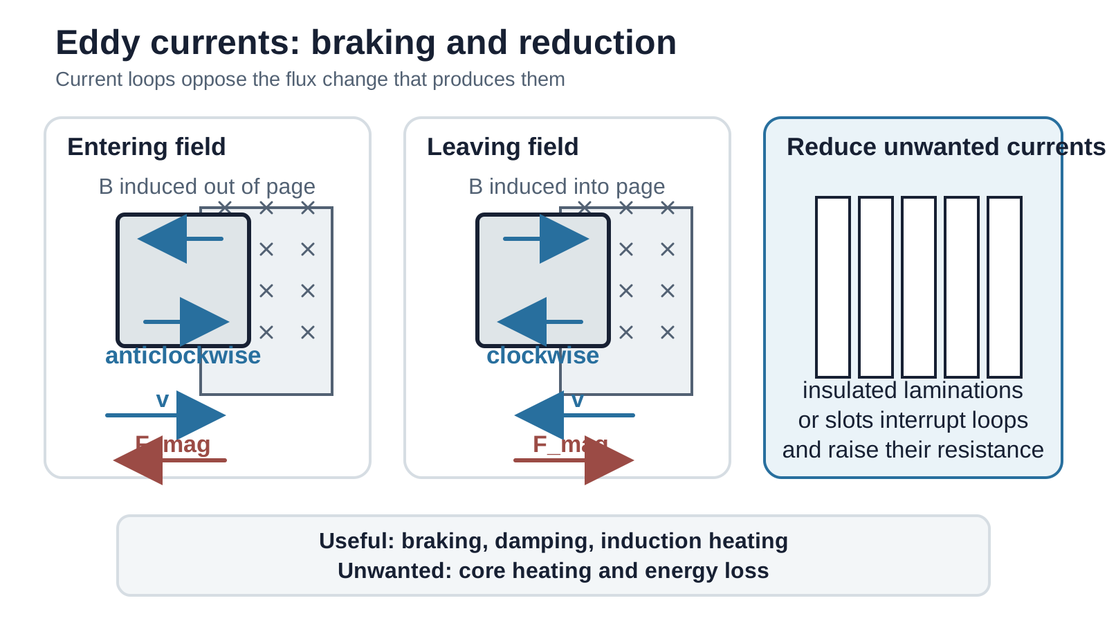
Figure: When a conducting plate enters or leaves a magnetic-field region, eddy currents produce magnetic effects that oppose the change and hence oppose the relative motion in this passive braking arrangement. Insulated laminations or slots interrupt large current paths and reduce heating.
Eddy currents can be useful in magnetic braking, damping, and induction heating. They can also waste energy as thermal energy in transformer cores. Laminating a core into electrically insulated sheets increases the resistance of possible loops and greatly reduces the currents.
10. Final concept map
Always ask three questions:
- What surface or circuit is being considered, and what is its chosen normal?
- How is its flux linkage changing?
- Is the circuit open, or can a sustained induced current flow?