Alternating Current Common Exam Traps
Overview
Alternating-current errors usually come from misidentifying a waveform quantity, using a formula outside its assumptions, or tracing a circuit direction incorrectly. Use this checklist after studying Alternating Current.
Core Ideas
- Name each quantity as instantaneous, peak, peak-to-peak, mean or rms.
- State whether a waveform is sinusoidal before using the factor.
- State “pure resistor” before using the in-phase power relations.
- In transformer and rectifier questions, trace cause and current direction rather than relying on a memorised picture.
- Separate official core material from enrichment claims.
Definition
An exam trap is a predictable error caused by using a familiar relation without checking its definition, reference direction or assumptions.
Why It Matters
The algebra in this topic is usually short. Careful interpretation therefore carries much of the assessment demand: one wrong choice between peak and rms, or one reversed transformer ratio, can invalidate an otherwise correct calculation.
Key Representations and Traps
1. Peak, peak-to-peak and rms
For a sinusoid,
The peak-to-peak value is not . Read the zero line before measuring a peak from a graph.
2. Period, frequency and angular frequency
One period is the interval between equivalent points with the same direction of change, not merely between any two zero crossings.
Use seconds for , hertz for , and for .
3. Ignoring the initial phase
The form starts at zero and initially rises. A graph beginning at a peak needs a different phase, for example . Do not force every sinusoid into the zero-phase sine form without shifting the time origin.
4. Mean value versus rms value
A symmetric sinusoidal current has zero cycle mean, but
RMS is not the mean magnitude. It is based on the mean square and is tied to the same heating power in a resistor.
5. Applying the sinusoidal rms factor to any waveform
The relation is not universal. For a square wave of values and , . Use the general mean-square definition for a non-sinusoidal waveform.
6. Concluding that zero mean current means zero power
For a pure resistor,
Current reversal does not make the heating power negative.
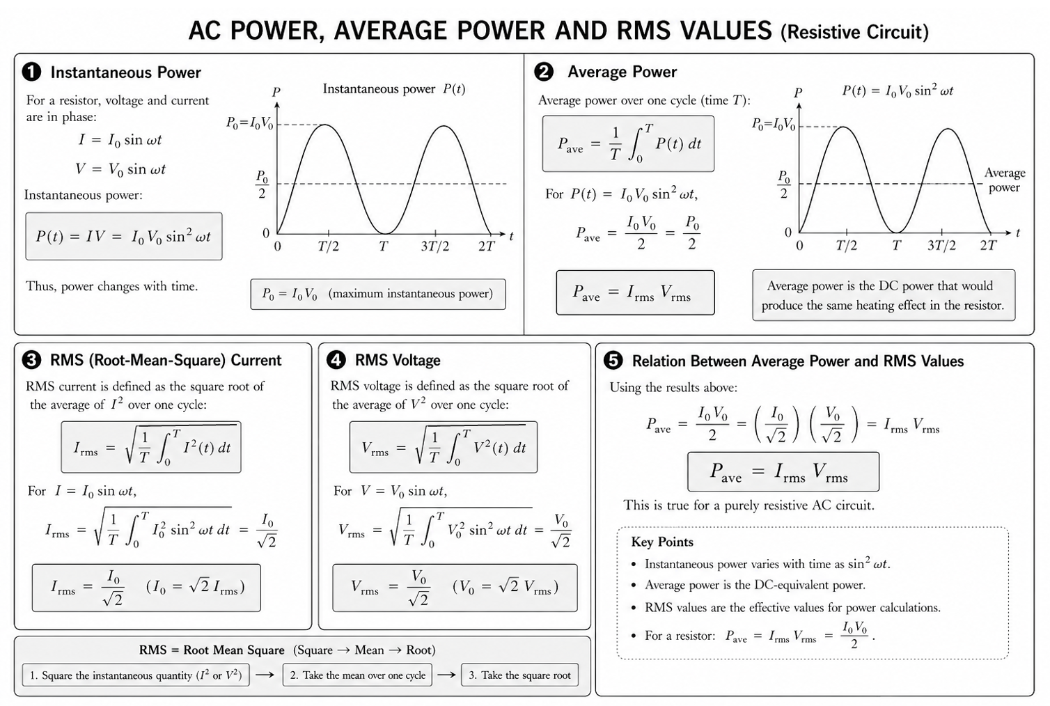
Figure: The power curve is non-negative and repeats twice in each current cycle. Its mean is half its maximum only for sinusoidal current in a resistor.
7. Confusing maximum and mean power
For in a resistor,
Do not describe as the appliance’s average power rating.
8. Using without a load condition
At this level,
is used for a pure resistive load, for which and are in phase. Do not extend it uncritically to arbitrary phase differences.
9. Reversing the transformer current ratio
For an ideal transformer,
A step-up transformer raises voltage but lowers current. It does not create power:
10. Assuming a universal secondary phase
The relative instantaneous polarity of the windings depends on their winding sense and chosen reference terminals. A turns ratio gives magnitudes; it does not by itself justify “the secondary is always out of phase”.
11. Forgetting the transformer mechanism
The complete explanation is:
Steady DC does not maintain a changing flux after the switching transient.
12. Reversing the diode or load-current direction
In single-diode half-wave rectification, first mark the source polarity for that half-cycle. Conventional current can pass only in the diode’s forward direction. It then returns from the load toward the source’s negative terminal.
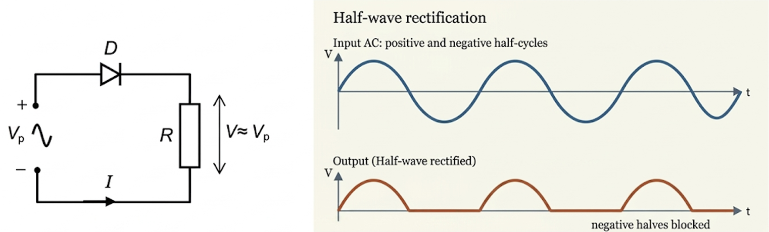
Figure: The conducting half-cycle and blocked half-cycle must be analysed separately. The output is one-directional but not constant.
13. Calling unsmoothed output steady DC
Half-wave rectification gives pulsating DC: its polarity is unchanged, but its magnitude varies and becomes zero during the blocked half-cycle.
14. Enrichment claims used as if they were core
The stated syllabus requires a single-diode half-wave rectifier. A bridge rectifier, full-wave pulse rate and capacitor smoothing are useful enrichment, but label them as such unless another syllabus section or question explicitly supplies them.
15. Transmission quantities mixed up — enrichment
For the simplified fixed-power, in-phase model,
Use the transmission-line voltage to find line current, not the later consumer voltage. Doubling current quadruples cable heating loss.
Quick Self-Check Checklist
- Is the stated value peak, peak-to-peak, instantaneous or rms?
- Is the waveform sinusoidal before I divide by ?
- Did I distinguish , and ?
- Is the load a pure resistor for the power formula used?
- Did I invert the transformer current ratio correctly?
- Did I trace the allowed diode-current path and output polarity?
- Have I labelled enrichment as enrichment?
- Are all times, frequencies, voltages and currents in consistent units?
Exam Relevance
Show assumptions alongside equations. A short statement such as “for a sinusoidal current”, “for a pure resistor”, or “for an ideal transformer” often distinguishes a physically valid derivation from formula substitution.
Links
Summary
The safest routine is:
- identify the waveform and the quantity type;
- state the physical model and assumptions;
- use consistent peak or rms quantities;
- check current direction and polarity;
- test whether the result has a sensible magnitude and unit.