Rectification
Branch note: This page develops the diode application introduced in Semiconductors and Diodes.
Overview
Rectification uses diode one-way conduction to turn an alternating input into a unidirectional output. The H2 core model is a single diode in series with a load, producing half-wave, pulsating DC.
Scope guide
The 9749 core requirement is to explain half-wave rectification using a single diode. Four-diode bridge rectification and capacitor smoothing are retained later as clearly labelled enrichment.
1. What rectification means
An alternating voltage changes polarity periodically. If connected directly to a resistor, it drives conventional current first one way and then the other.
Rectification is the production of a unidirectional output from an alternating input. A diode can do this because it conducts strongly in forward bias and blocks current in reverse bias under the ideal-diode model.
The output of a simple rectifier is not constant. It has one polarity but a magnitude that repeatedly rises and falls, so it is called pulsating direct voltage or pulsating DC.
Core Ideas
- A forward-biased diode conducts in the ideal model; a reverse-biased diode blocks.
- For the shown single-diode circuit, one input half-cycle reaches the load and the other is blocked.
- The output is unidirectional but time-varying, so it is pulsating DC rather than steady DC.
- Bridge rectification and capacitor smoothing are enrichment beyond the stated single-diode core.
2. Define the reference directions first
Before deciding which half-cycle appears at the output:
- mark the diode orientation;
- label the output terminals across the load resistor;
- define which output terminal is positive;
- use conventional current, from higher potential to lower potential in the external circuit.
Reversing the diode reverses which half-cycle is passed. Therefore, “the positive half-cycle always passes” is not a complete rule; it is true only for the specified diode orientation and output polarity.
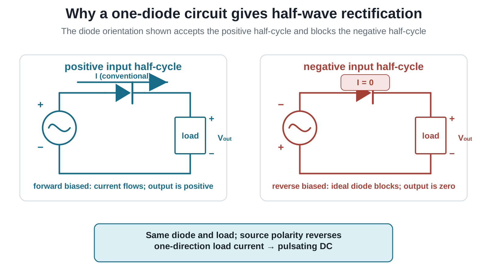
Figure: The source-terminal and markers show the instantaneous polarity. For the diode orientation shown, the conducting state drives conventional current through the load and makes the marked upper output terminal positive. When the source polarity reverses, the ideal diode blocks, so the current and the p.d. across the load are both zero.
3. Single-diode half-wave rectifier
Consider an ideal diode and load resistor connected in series to a sinusoidal source. Let
and choose the diode orientation so that the labelled positive input half-cycle forward biases it.
Positive input half-cycle
- The source makes the diode’s anode at higher potential than its cathode.
- The diode is forward biased and behaves approximately like a closed switch in the ideal model.
- Conventional current flows through the load in the labelled direction.
- The output across the load follows the positive input half-cycle.
Negative input half-cycle
- The source polarity reverses.
- The diode is reverse biased and behaves approximately like an open switch.
- Current through the series circuit is approximately zero.
- The output p.d. across the load is approximately zero.
Compare the two states
| Input state for the shown reference | Source polarity at the diode side | Diode state | Ideal load current | Output across the marked load terminals |
|---|---|---|---|---|
| positive half-cycle | upper source terminal positive | forward biased; conducts | flows in the marked direction | positive pulse |
| negative half-cycle | upper source terminal negative | reverse biased; blocks | zero | zero |
This table applies to the displayed diode orientation and output reference. Reversing the diode would pass the opposite input half-cycle.
For this stated orientation and ideal model,
Equivalently,
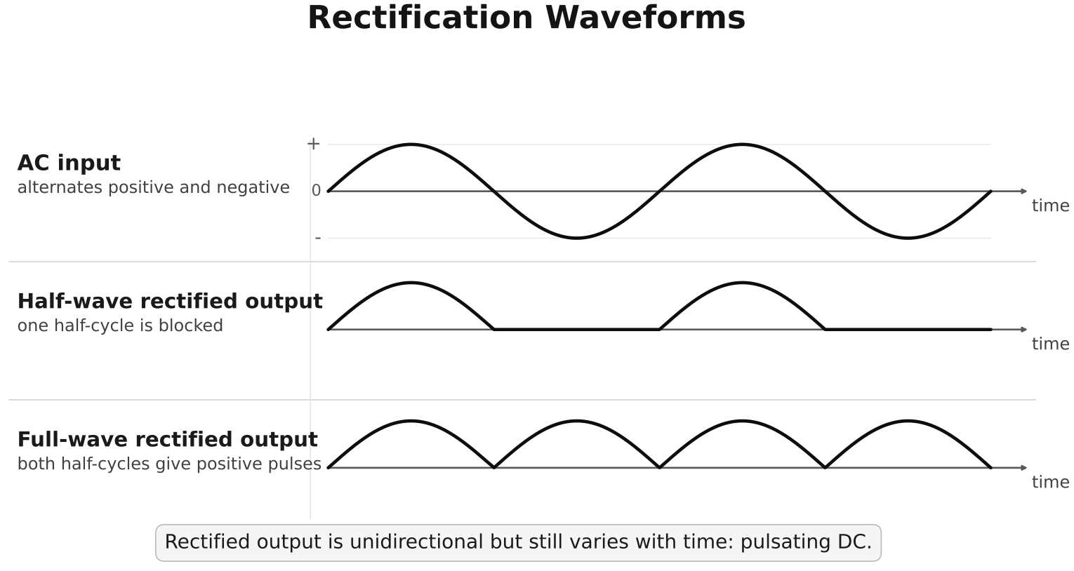
Figure: The upper trace is the sinusoidal input and the lower trace is the half-wave output for the stated diode orientation. Their time landmarks are vertically aligned: each positive input half-cycle gives one positive output pulse, while each negative half-cycle gives zero output. The output is unidirectional but time-varying.
4. What remains unchanged and what changes
For an ideal single-diode half-wave rectifier:
- the time between successive output pulses is one input period ;
- the pulse repetition frequency equals the input frequency ;
- one input half-cycle is blocked;
- the load current does not reverse direction;
- the mean output is non-zero, but the instantaneous output is not constant.
Do not describe the output as an alternating voltage merely because it varies with time. “Alternating” means that the polarity or current direction reverses; this output does not.
5. Ideal and practical diode models
Ideal-diode model
- zero p.d. across the diode while conducting;
- zero current while reverse biased.
The load output therefore equals the passed input half-cycle.
Constant forward-drop model
If a question specifies a forward drop , conduction occurs only when the input is large enough to forward bias the diode. During conduction,
for the orientation shown. Use this only when a non-ideal model or diode drop is stated or clearly required.
6. Worked reasoning example
A peak sinusoidal source is connected to an ideal single-diode half-wave rectifier and resistor. The orientation passes the labelled positive half-cycles.
- At the positive peak, .
- At the negative peak, the diode is reverse biased and .
- The output polarity across the resistor never reverses.
If a constant diode drop were explicitly specified, the output near the positive peak would instead be approximately
7. Common mistakes
- saying that the diode “removes AC completely”;
- calling a time-varying unidirectional output steady DC;
- assuming the positive half-cycle passes without checking diode orientation;
- tracing electron flow when the question expects conventional current;
- drawing a negative output pulse while retaining the stated positive output reference;
- claiming current flows through the reverse-biased ideal diode;
- applying a drop when the question specifies an ideal diode;
- treating bridge rectification as part of the required single-diode explanation.
8. Exam method
For each half-cycle, write a four-link explanation:
Then sketch the output directly below the input using the same time scale. Keep the blocked half-cycle on the zero axis rather than drawing it as a negative pulse.
Exam Relevance
Rectification questions usually reward explicit half-cycle reasoning. Mark the source polarity, determine diode bias, trace conventional current if it flows, and then infer the load p.d. for the chosen output reference.
Enrichment: full-wave bridge rectification
Beyond the stated single-diode core
A bridge rectifier uses four diodes. During each input half-cycle, a different pair conducts, but the current through the load has the same direction.
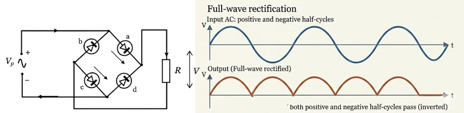
Figure: Enrichment bridge-rectifier model. A bridge redirects both source half-cycles so that the load receives a pulse during each half-cycle. The conducting pair changes when source polarity reverses.
For a sinusoidal input of frequency , full-wave output pulses repeat at . This gives shorter gaps between pulses than a half-wave rectifier. It does not, by itself, make the output constant.
| Property | Single-diode half-wave | Four-diode full-wave bridge |
|---|---|---|
| Input half-cycles used | one | both |
| Output pulse frequency | ||
| Load-current direction | one direction | one direction |
| Output without smoothing | pulsating | pulsating |
Enrichment: capacitor smoothing
Beyond the stated rectification core
A capacitor connected across the load can reduce variation in the rectified output.
Near an output peak, the capacitor charges. When the rectified source voltage later falls below the capacitor voltage, the capacitor discharges through the load, helping to maintain the output between peaks. The voltage still normally contains some variation called ripple.
Greater capacitance or a larger load resistance generally increases the discharge time constant and reduces ripple, all else equal. Smoothing does not create energy and does not guarantee perfectly constant voltage.
Links
Summary
A single diode conducts during one source half-cycle and blocks during the opposite half-cycle. The load therefore receives a unidirectional sequence of pulses: half-wave-rectified, pulsating DC. Which half-cycle appears depends on diode orientation and the chosen output polarity. Bridge rectification and capacitor smoothing are useful enrichment, not substitutes for mastering the required single-diode explanation.