Force Diagrams and Resolution
Branch note: A correct representation should make the equations almost inevitable.
Overview
This branch note develops free-body diagrams, component resolution, sign conventions and vector-polygon reasoning for force problems.
Core Ideas
- Choose the system before drawing force arrows.
- Draw only external forces on the chosen body.
- Resolve angled forces along useful perpendicular axes.
- Components replace the original vector in equations.
- A closed force polygon shows zero resultant force, not moment equilibrium.
1. Choose the system first
Before drawing any arrow, complete the sentence:
“I am analysing ______.”
The answer may be one block, one person, a beam, or a combined system. The system choice determines which forces are external.
- A force exerted by something outside the system is external and appears on the free-body diagram.
- A force between two parts both inside the system is internal and is omitted from the free-body diagram of the combined system.
For two blocks connected by a string, tension is external when either block is analysed alone, but internal when both blocks and the connecting string are treated as one system.
2. What belongs on a free-body diagram?
A free-body diagram shows every real external force on the chosen body, with correct direction and a meaningful label.
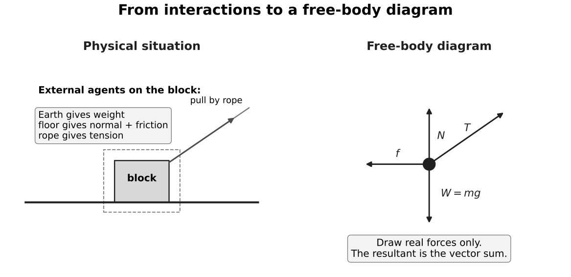
Figure: The physical scene establishes the interactions; the isolated-body diagram keeps only forces acting on the block. Weight, surface forces and the applied pull have different agents. The acceleration and resultant may be calculated later, but neither is an additional interaction force.
Include
- weight by Earth;
- contact forces by surfaces;
- tension by a taut string;
- elastic force by a spring;
- drag or upthrust by a fluid;
- relevant field forces.
Do not include
- velocity or acceleration arrows as forces;
- “motion force”;
- the resultant as an extra arrow;
- components as well as the original force;
- a Newton’s-third-law partner acting on another body.
3. Choose axes and signs
Axes are mathematical choices, not physical forces. Choose them to reduce the number of angled components.
- For horizontal motion, horizontal and vertical axes are usually convenient.
- For an incline, choose one axis parallel and one perpendicular to the plane.
- State the positive direction before writing signed equations.
Newton’s second law is then applied separately:
A negative answer means the actual component points opposite to the chosen positive direction.
4. Resolving one force
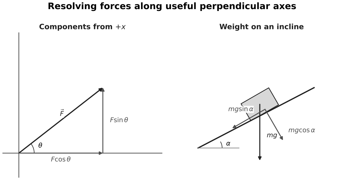
Figure: In the left panel, is measured from , so is adjacent to the angle and is opposite. The two component vectors add to the original vector. In the right panel, the axes are rotated with the incline; the geometry changes the component labels but never changes the vertical direction of weight.
If is measured from the positive -axis,
If the angle is instead measured from the -axis, the sine and cosine roles interchange. A reliable method is to sketch the component triangle and identify the adjacent and opposite sides.
Replace, do not duplicate
After resolution, use and in component equations instead of . Counting all three would double-count the same force.
5. Weight components on an incline
For a plane at angle above horizontal,
acts down the plane, and
acts into the plane.
The normal-force result
is valid only if:
- the body remains in contact with the plane;
- perpendicular acceleration is zero; and
- no other force has a perpendicular component.
On a smooth incline, there is no friction. An unsupported block therefore accelerates down the plane; it does not “rest” merely because the plane is smooth.
6. Worked example: accelerated block on an incline
A block slides down a smooth plane inclined at to horizontal. Find its acceleration and the normal force.
Choose downslope positive. Along the plane,
so
Perpendicular to the plane, :
giving
The two equations answer different questions because they refer to perpendicular directions.
7. Physical diagram versus force polygon
A physical diagram shows where forces act on a body. A vector polygon moves force vectors parallel to themselves and places them head-to-tail to show vector addition.
For three forces in translational equilibrium, the vector triangle closes:
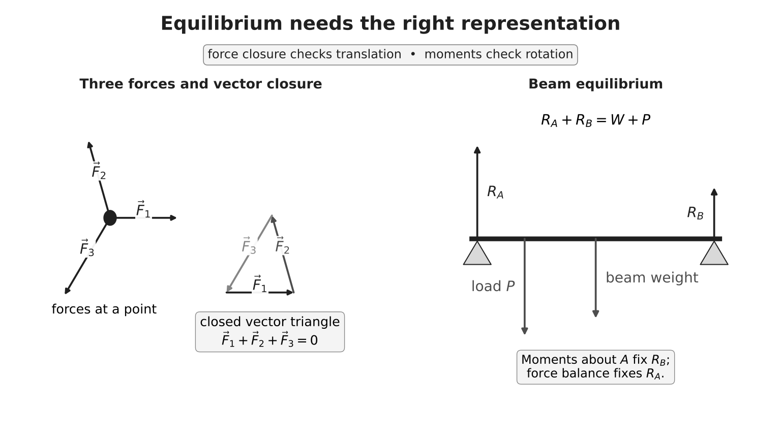
Figure: The three forces originate from their physical lines of action in the object diagram. In the separate force triangle, arrows are translated without rotation and placed head-to-tail. Closure represents zero resultant force; it does not represent the physical positions where the forces act.
8. Multi-body strategy
For connected bodies:
- draw a separate free-body diagram for each body when an internal force such as tension is required;
- use a combined system when internal forces can be eliminated;
- use the same acceleration constraint only when the connection and pulley model justify it;
- never assume equal tension without stating the light-string/smooth-pulley model.
Exam Relevance
Most force-question errors come from representation rather than algebra. In exams, state the chosen system, draw real external forces, choose axes, then write one component equation per direction.
9. Final checklist
- Have I named the system?
- Does every force have a real agent?
- Are all arrows forces on the system?
- Is weight vertical?
- Is normal force perpendicular to the contact?
- Is friction based on relative slip tendency?
- Have components replaced the original vector?
- Are axes and signs explicit?
- Have I written one equation per direction?