Dynamics
Topic hub: Begin here, then use the linked branch notes for focused derivations, worked examples and common traps.
Overview
Kinematics describes how position, velocity and acceleration change. Dynamics explains how interactions produce those changes.
The chapter has one recurring question:
For the system I have chosen, what external forces or external impulses change its motion?
A system is the body or collection of bodies selected for analysis. Forces between parts of that system are internal; forces exerted by objects outside it are external. Changing the system boundary changes which forces appear in the equation.
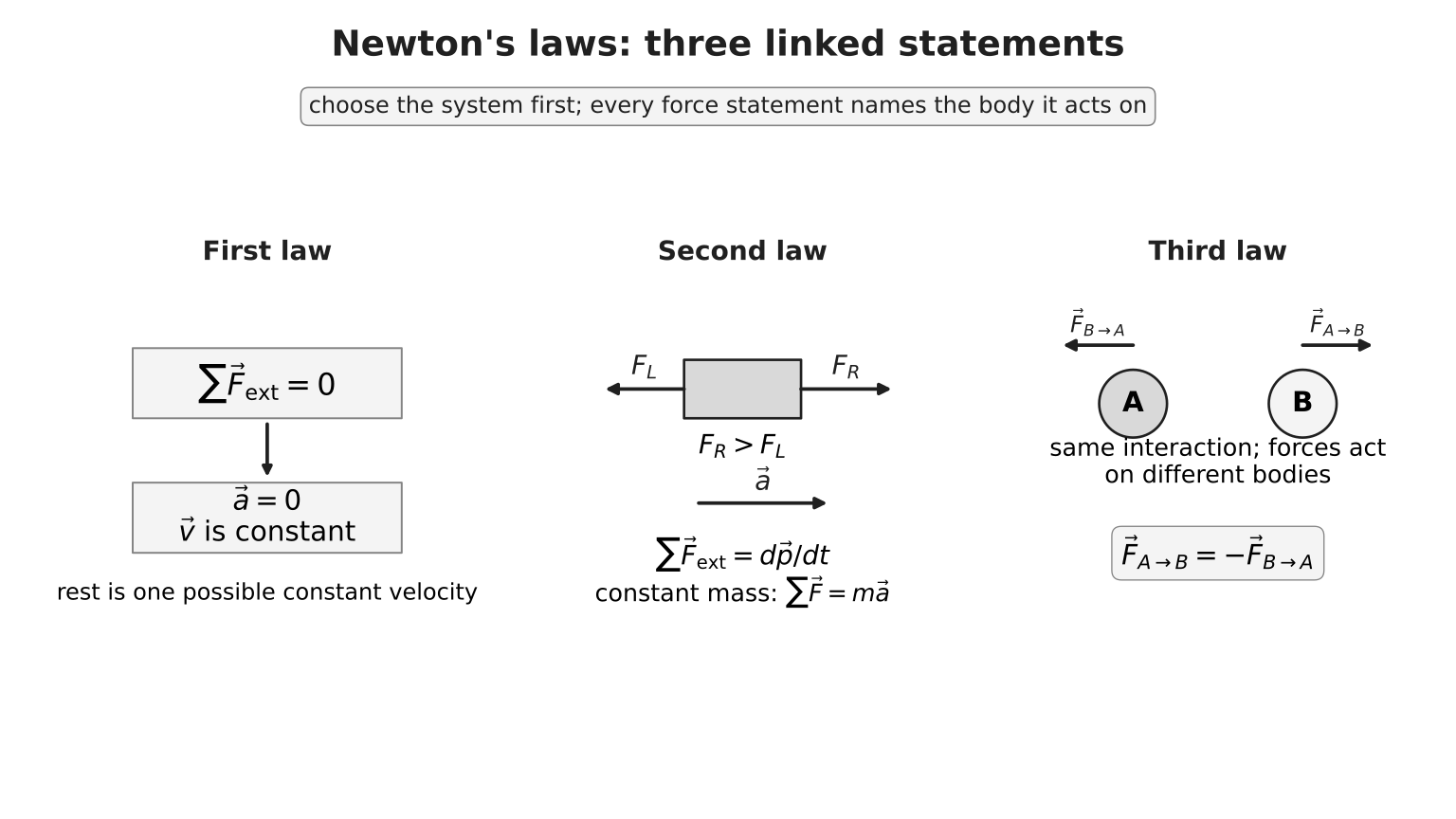
Figure: Newton’s first law describes motion when the resultant external force is zero. The second law connects a non-zero resultant to the rate of change of momentum. The third law relates the two forces within one interaction, but those forces act on different bodies. Read the body labels before deciding whether forces can be combined in one equation.
Core Ideas
- Dynamics begins by choosing a system and identifying the external forces or external impulses that change its motion.
- Newton’s second law is best read as a resultant-force statement: , with for constant mass.
- Newton’s third-law pairs act on different bodies; balanced forces act on the same body and cancel only under suitable acceleration conditions.
- Momentum is conserved for a chosen system only when the resultant external impulse on that system is zero or negligible.
- Collision questions usually combine momentum conservation with one extra model condition, such as sticking, kinetic-energy conservation, or the one-dimensional elastic relative-speed condition.
Newton’s laws of motion
Newton’s laws are stated in an inertial reference frame: a frame in which a force-free body moves with constant velocity. Any non-rotating frame moving at constant velocity relative to an inertial frame is also inertial. For ordinary H2 laboratory problems, the Earth frame is treated as approximately inertial.
2.1 First law: the zero-resultant case
An object remains at rest or continues moving with constant velocity in a straight line unless a non-zero resultant external force acts on it.
Zero resultant force does not mean zero velocity. A trolley moving steadily on a level track can have zero resultant force.
Inertia is the resistance of a body to a change in its velocity. Mass measures this inertia: for the same resultant force, a larger mass has a smaller acceleration.
2.2 Momentum: a measure of motion
Mass is a scalar measure of inertia, in kilograms: for the same resultant force, a larger mass has a smaller acceleration.
The linear momentum of a body is
where is mass in kilograms and is velocity. Momentum is a vector in the direction of velocity, with SI unit
In one dimension, choose a positive direction and use signed velocities. A negative momentum indicates motion opposite to the chosen positive direction; it is not a “negative amount of motion”.
2.3 Second law: the resultant changes momentum
For a particle or a fixed collection of matter, the resultant external force equals the rate of change of momentum:
For a body of constant mass,
Thus the acceleration vector is always in the direction of the resultant force, not necessarily in the direction of velocity.
Enrichment — variable-mass warning. Rockets and bodies gaining or losing material are open-system problems. Simply expanding for the remaining body does not by itself give a complete equation because momentum crosses the system boundary. Detailed momentum-flux treatment is beyond H2 Physics 9749.
2.4 Third law: one interaction, two bodies
If body A exerts a force on body B, body B simultaneously exerts a force of the same interaction type on body A, equal in magnitude and opposite in direction:
The subscripts matter. The two forces:
- act on different bodies;
- are equal and opposite even if the bodies have different accelerations;
- act along the same line for the contact or central interactions used here;
- do not cancel on the free-body diagram of either body alone.
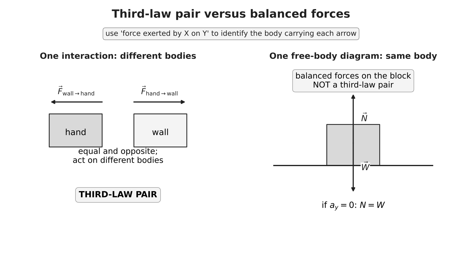
Figure: In the interaction panel, the hand-on-wall and wall-on-hand forces form a third-law pair because they belong to the same interaction and act on different bodies. In the balance panel, the normal contact force and weight act on the same block; they may be equal when vertical acceleration is zero, but they are not a third-law pair. Each partner force is found by reversing the “exerted by … on …” description.
Mass, weight and scale reading
Weight is the gravitational force on a mass:
Near Earth’s surface, is vertically downward and has magnitude approximately . Weight is measured in newtons and can change if gravitational field strength changes; mass does not.
A scale does not measure weight directly. It measures the contact force between the person and the scale. This contact-force magnitude is called the scale reading or apparent weight.
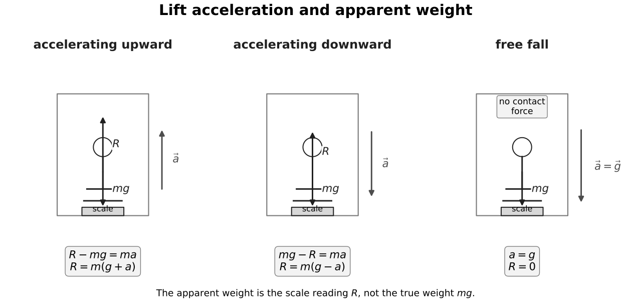
Figure: The person’s true weight is unchanged across the three panels. The scale reading is the upward normal-force magnitude . It exceeds for upward acceleration, is below for downward acceleration, and becomes zero in free fall because the person and scale accelerate together under gravity and lose contact pressure.
With upward chosen positive,
Hence, while the person remains in contact with the scale,
For downward acceleration, the contact model requires . At , . A calculation giving means that maintained contact is impossible: the scale cannot pull the person downward. Apparent weightlessness does not mean gravity is absent.
A reliable dynamics workflow
For every force problem:
- Choose the system. State exactly which body or bodies are included.
- Draw the physical situation, then a separate free-body diagram for each chosen system.
- Include only real external forces on that system. Do not draw velocity, acceleration or a separate “resultant force” as extra forces.
- Choose perpendicular axes and positive directions. Axes along likely acceleration or along a surface are often useful.
- Resolve forces, not the body. Replace a force by components only when using component equations.
- Write one second-law equation per independent axis:
- Solve, then check sign, direction, units, limiting cases and whether the assumed contact/string condition remains possible.
The mass on the right-hand side is the mass of the system represented by that equation.
Standard applications
5.1 Connected bodies and system choice
For an ideal string-and-pulley model:
- the string is light, inextensible and taut;
- the pulley is smooth and light;
- the tension magnitude is the same throughout the string;
- connected bodies have equal acceleration magnitudes along the string.
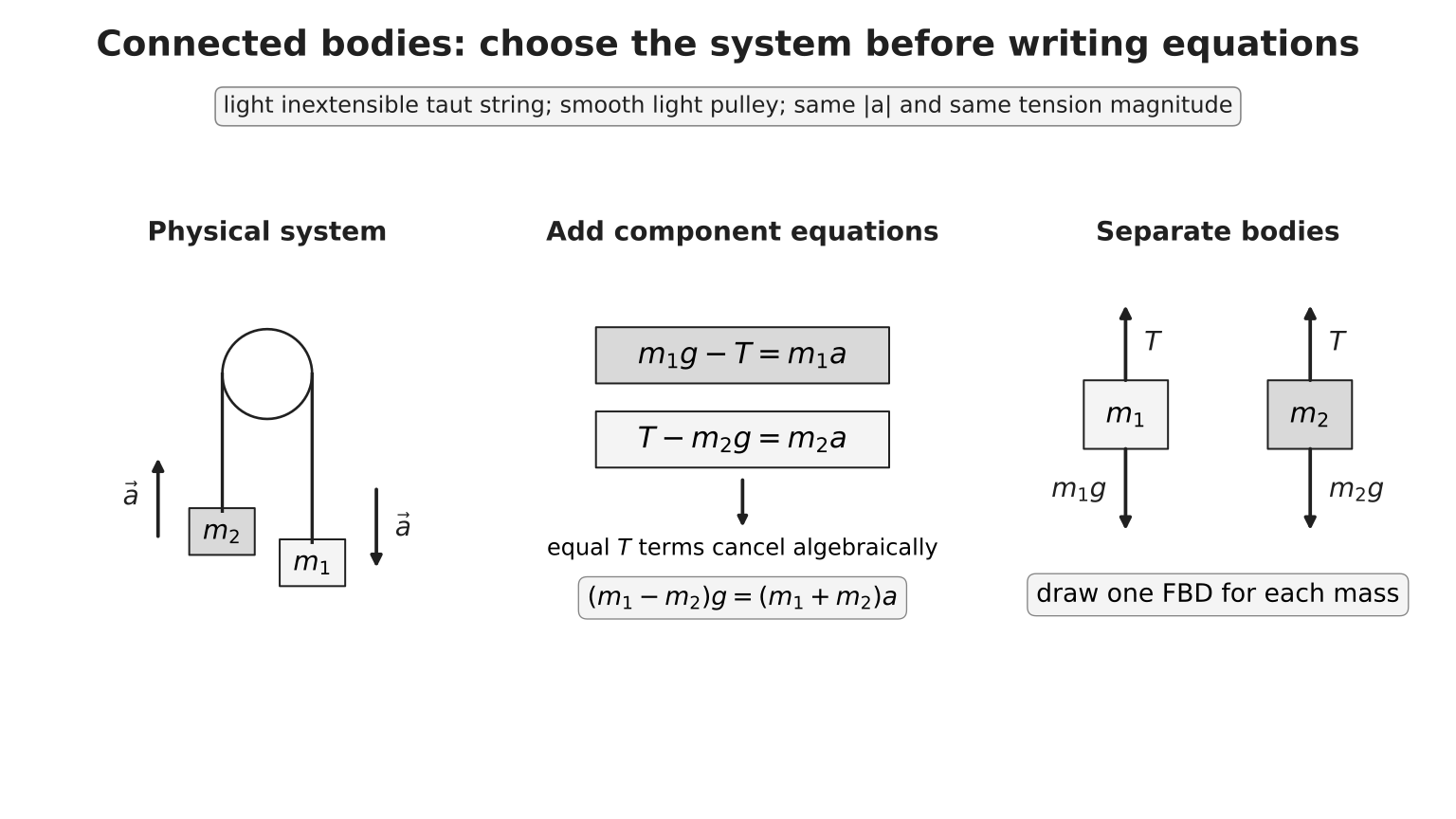
Figure: Draw a separate free-body diagram for each mass. Choose positive along each mass’s motion: downward for and upward for . The inextensible-string constraint gives equal acceleration magnitudes, not the same acceleration vector, and the ideal-string model gives equal tension magnitudes. Adding the two signed path equations then cancels the equal terms algebraically.
For , take downward and upward as positive along their respective paths:
Adding the two equations eliminates the equal tension terms:
For and ,
and
The result passes two checks: , and .
5.2 Motion on an inclined plane
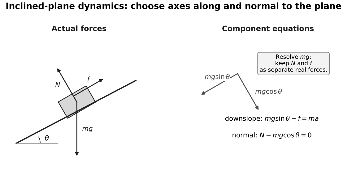
Figure: The weight remains vertically downward. Resolving it along axes parallel and perpendicular to the plane gives downslope and into the plane. The normal reaction equals only when perpendicular acceleration is zero and no other force has a perpendicular component. Friction points opposite the actual or impending relative motion, not automatically opposite the velocity arrow chosen by the diagram author.
Taking downslope as positive for a block that remains in contact with the plane,
if friction of magnitude acts upslope. Perpendicular to the plane,
only under the conditions stated in the caption.
Impulse and change in momentum
The impulse of a specified force is
For a constant specified force, this becomes . The impulse–momentum theorem concerns the resultant force:
This follows from Newton’s second law:
In a one-dimensional force-time graph, the signed area between the resultant-force curve and the time axis equals the signed impulse. Area below the axis is negative under the chosen convention.
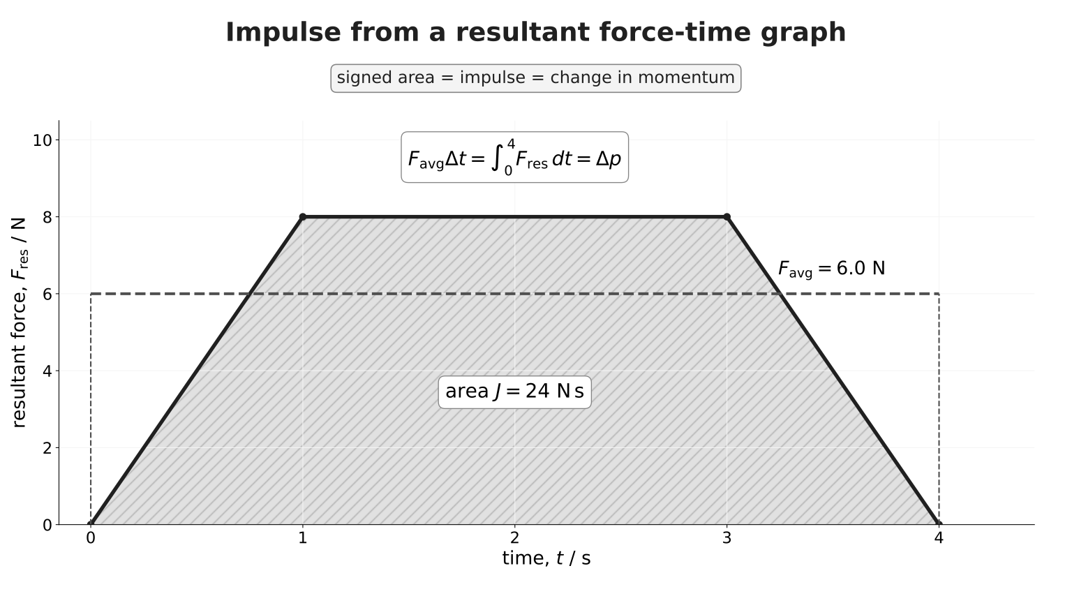
Figure: The shaded area under the piecewise-linear resultant-force pulse is its impulse. The dashed constant line is the average resultant force: its rectangle has the same signed area over the same interval. Therefore . A high peak force is not itself an impulse; both force and duration determine the momentum change.
Worked sign example: a rebounding ball
Choose motion toward a wall as positive. A ball changes velocity from to :
The impulse is away from the wall. If contact lasts ,
The negative sign supplies the direction; do not discard it before interpreting the answer.
For the same , increasing the stopping time reduces the magnitude of the average resultant force. This is the principle behind airbags, crumple zones and bending the knees on landing.
Conservation of linear momentum
For a multi-body system,
Over an interaction interval,
Internal forces occur in equal-and-opposite third-law pairs and act for the same time, so their impulses cancel in the total system momentum. Therefore:
The total linear momentum of a system remains constant when the resultant external impulse on the system is zero or negligible.
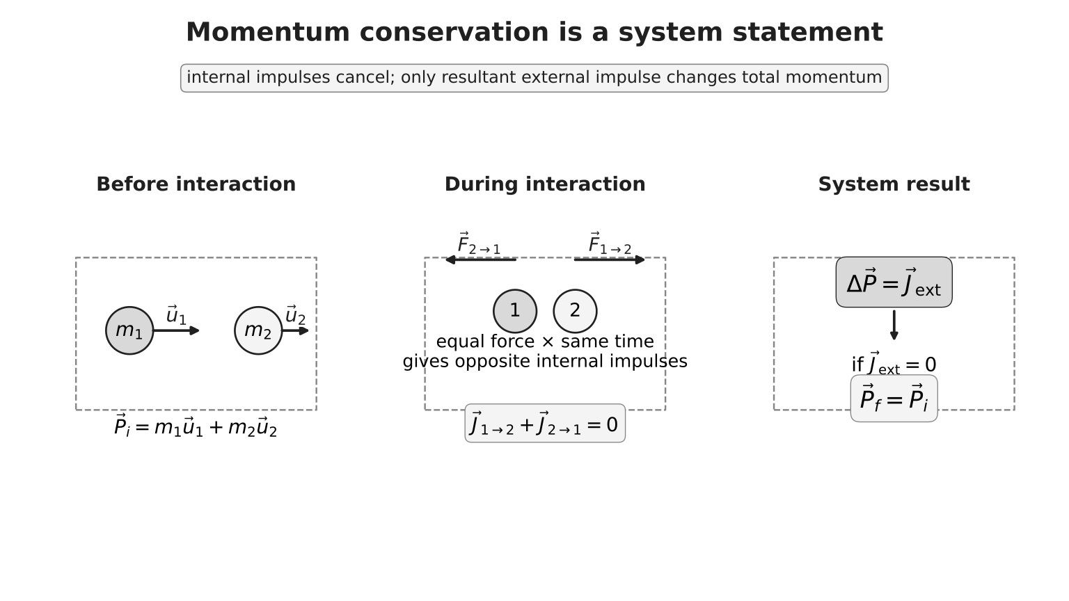
Figure: During the collision, the internal forces give equal-and-opposite impulses to the two bodies, transferring momentum between them without changing the total. Only an external impulse changes the system total. In short collisions, gravity and support may be present but their impulses can be negligible compared with the collision impulses; this approximation must be stated or justified.
In one dimension, choose one positive direction and write all velocities with signs:
Momentum conservation is a statement about a specified system, not a claim that each body’s momentum is unchanged.
One-dimensional collisions
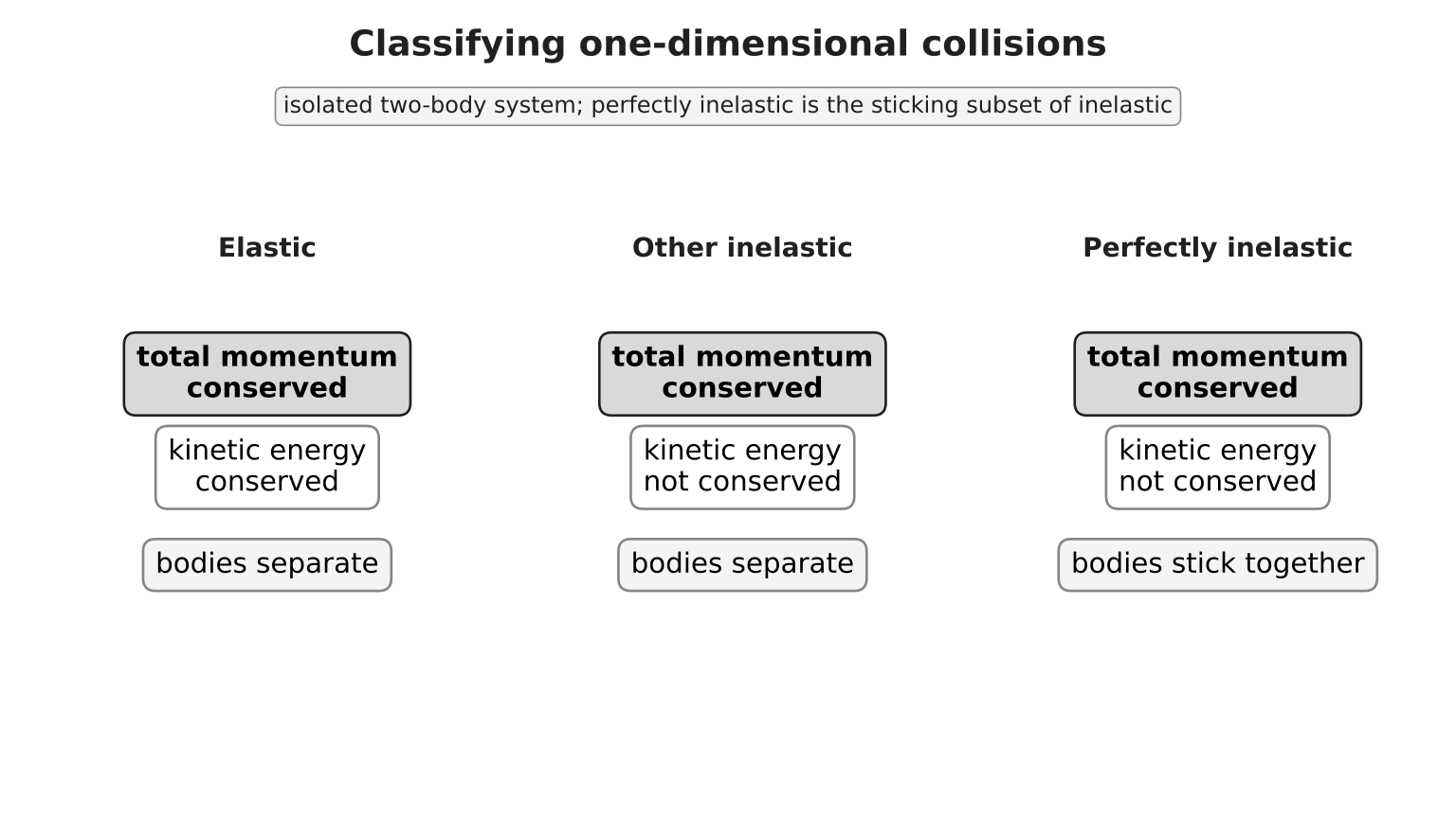
Figure: All three isolated-system outcomes conserve total momentum. An elastic collision also conserves total kinetic energy. “Other inelastic” denotes inelastic collisions in which the bodies separate; a perfectly inelastic collision is the special inelastic case in which they stick and share one final velocity. The categories describe what is conserved and whether the bodies separate or stick; they do not determine the numerical velocities by themselves.
8.1 Elastic collision
For a perfectly elastic collision:
and
For two bodies in one dimension, these imply
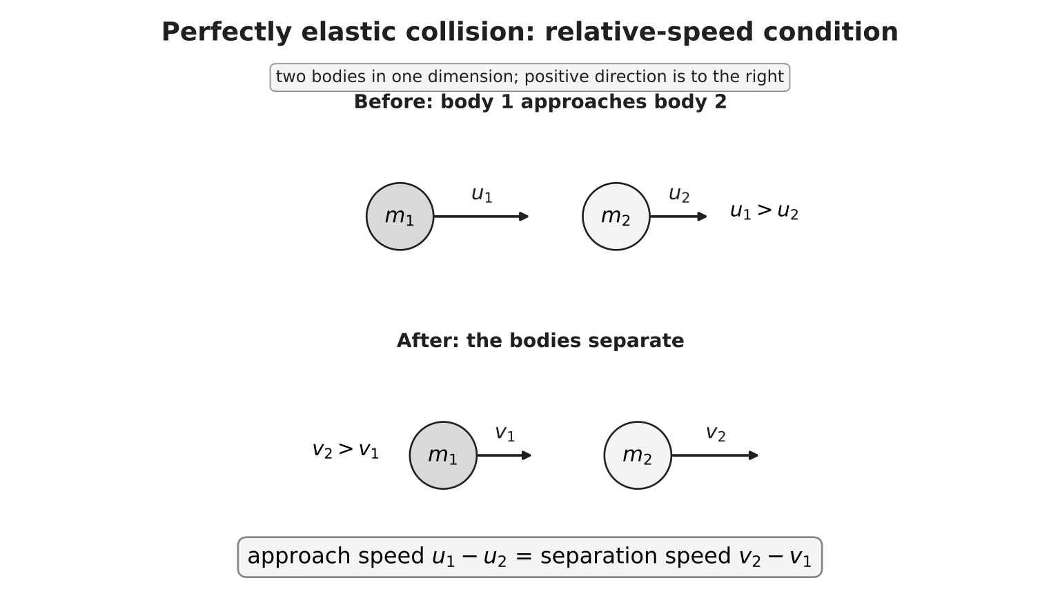
Figure: Body 1 starts behind body 2 and approaches it, with positive direction to the right. Before impact, ; after a perfectly elastic collision in which they separate to the right, . Thus is the approach speed and is the separation speed. The signed equation is valid only for a perfectly elastic collision between two bodies in one dimension with consistent velocity labels.
This is a signed-velocity equation. More generally, use magnitudes when identifying the geometry: if body 1 is behind body 2 before impact, the approach speed is and the separation speed is . For the ordering shown in Figure 9, the equation states
Do not use it for an inelastic collision.
Worked example. A trolley moving at collides elastically with a trolley initially at rest.
Solving gives
The first trolley rebounds. The kinetic-energy check gives before and after.
8.2 Inelastic and perfectly inelastic collisions
In an inelastic collision, total momentum is conserved for an isolated system but total kinetic energy is not.
In a perfectly inelastic collision, the bodies stick and move with common velocity :
Worked example. A trolley at sticks to a trolley initially at rest:
The initial and final kinetic energies are
The decrease becomes internal energy, deformation, sound or other forms.
Scientific clarification. In ordinary passive collisions, an inelastic collision loses kinetic energy. More generally, “inelastic” means kinetic energy is not conserved; an interaction that releases stored internal energy can increase kinetic energy. H2 questions normally make the physical context clear.
Choosing the method
| Information or aim | Most direct starting point |
|---|---|
| Forces and acceleration at an instant | |
| Force varies with time | |
| Short collision or explosion | momentum conservation for a justified system |
| Perfectly elastic 1D collision | momentum plus relative-speed condition |
| Bodies stick after impact | momentum plus a common final velocity |
| Need energy converted in a collision | compare total kinetic energy before and after |
Common misconceptions
- “No force means no motion.” Zero resultant force means zero acceleration, so velocity is constant and may be non-zero.
- “Resultant force is another arrow.” It is the vector sum of the real forces already drawn.
- “Equal and opposite means third-law pair.” A third-law pair must act on different bodies and arise from the same interaction.
- “Normal force always equals weight.” This is true only under particular perpendicular-force and acceleration conditions.
- “A moving lift has a changed scale reading.” Scale reading depends on acceleration, not velocity.
- “Connected masses have the same acceleration vector.” They have equal acceleration magnitudes along an inextensible string; in the hanging arrangement shown, their acceleration vectors point in opposite spatial directions.
- “Area under any force graph equals the body’s momentum change.” It equals only when the plotted force is the resultant force; otherwise it is the impulse of that particular force.
- “Momentum is conserved in every chosen system.” The resultant external impulse on that system must be zero or negligible.
- “Kinetic energy is conserved in all collisions.” Only elastic collisions conserve total kinetic energy.
- “Negative velocity is impossible.” It means motion opposite to the chosen positive direction.
- “Elastic relative-speed equation works for all collisions.” It is restricted to perfectly elastic two-body motion in one dimension.
Exam Relevance
For H2 Dynamics questions, expect to:
- draw free-body diagrams and write signed force equations for a clearly chosen system;
- apply Newton’s laws to connected bodies, lifts and inclined-plane situations;
- use force-time graph area as impulse and connect impulse to change in momentum;
- justify when linear momentum is conserved by checking the external impulse on the chosen system;
- distinguish elastic, inelastic and perfectly inelastic collision models before choosing equations.
Formula and condition summary
| Relationship | Meaning and condition |
|---|---|
| linear momentum of one body | |
| Newton’s second law | |
| constant-mass body | |
| one interaction, two bodies | |
| gravitational force on a mass | |
| impulse-momentum theorem | |
| total system momentum change | |
| zero or negligible resultant external impulse | |
| perfectly elastic two-body collision in 1D |
Links
- Newton’s Laws of Motion
- Free-Body Diagrams and Force Analysis
- Newtonian Dynamics Applications
- Momentum and Impulse
- Momentum Conservation and Collisions
- Dynamics Methods and Non-Constant Forces (optional enrichment)
- Forces
- Kinematics
- Vectors
- Work, Energy and Power
- Circular Motion
Provenance
- source anchor: Dynamics Lecture Anchor Notes Main
- active scope: H2 Physics 9749 syllabus for examination in 2026, Dynamics 3(a)–(k)
- revised draft prepared under
docs/physics_gpt_wiki_notes_regeneration_workflow.md