Alternating Current Generators Common Exam Traps
Overview
Use this checklist after learning the simple rotating-coil model. Most errors come from an undefined angle, a missing reference polarity, or confusion between flux linkage and its rate of change.
Core Ideas
- Define from the coil normal.
- Use for flux linkage and for flux through one turn.
- Use the gradient of the flux-linkage graph to infer emf.
- Distinguish instantaneous, peak and rms emf.
- Treat slip rings as contacts, not as the cause of alternating output.
- State the one-pole-pair condition before equating electrical and rotational frequency.
Definition
An exam trap is a predictable error caused by applying a valid equation with an unstated or incompatible convention.
Why It Matters
Generator questions combine geometry, differentiation, component functions and energy conservation. A correct formula can still give a wrong graph if the angle or terminal reference is unclear.
Key Representations and Traps
1. Measuring the wrong angle
For
is the angle between and the coil’s area vector, which is normal to the coil plane. If a question gives the angle between the plane and , convert it first.
2. Confusing flux and flux linkage
For one turn,
For turns,
Do not omit or multiply by it twice.
3. Thinking maximum flux linkage gives maximum emf
At a flux-linkage maximum or minimum, the graph is horizontal and emf is zero. At a zero crossing, the gradient magnitude and emf magnitude are greatest.
4. Memorising a phase sign without a reference
One stated convention gives
Swapping terminal labels changes the emf sign. Use the stated polarity and .
5. Confusing peak and instantaneous emf
is the peak. The instantaneous emf is
At under the chosen convention, is nonzero but .
6. Confusing peak and rms emf
For a sinusoidal output,
Do not use the peak value in a calculation that requires rms voltage.
7. Giving slip rings the wrong function
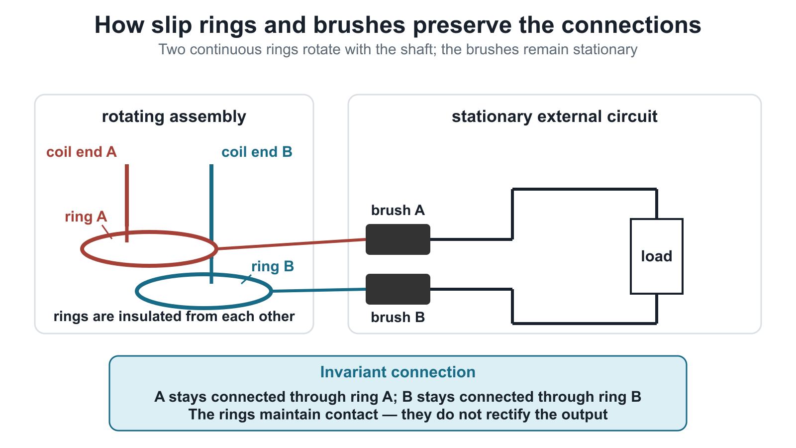
Figure: Each coil end remains connected to its own continuous ring. The brushes are stationary contacts. The rings do not swap the coil-end connections and do not rectify the output.
8. Assuming current exists on open circuit
Changing flux linkage induces emf even when the external circuit is open. Sustained external current requires a complete conducting circuit.
9. Using universally
For the simple one-pole-pair model,
Enrichment: With pole pairs, .
10. Changing , or and also changing frequency
, and scale peak emf but do not change rotation rate. A change in changes both peak emf and, for the same pole arrangement, output frequency.
11. Forgetting the energy source — enrichment
A generator converts mechanical input energy into electrical output energy. When load current increases, the magnetic torque opposing rotation increases. Maintaining the same speed therefore requires greater driving torque and mechanical input power.
12. Confusing generator and transformer
| Generator | Transformer |
|---|---|
| mechanical rotation changes flux linkage | alternating primary current changes core flux |
| converts mechanical to electrical energy | transfers electrical energy between circuits |
| rotating coil in the simple model | stationary coils on a common core |
13. Confusing slip rings with a split-ring commutator — enrichment
Slip rings preserve coil-end connections, so the alternating polarity reaches the external circuit. A split-ring commutator swaps the external connections every half-turn to make the external current unidirectional in a simple DC machine.
Quick Self-Check
- Did I define the angle from the coil normal?
- Did I distinguish from ?
- Did I use the negative gradient of flux linkage?
- Is the value instantaneous, peak or rms?
- Did I identify the terminal-polarity convention?
- Did I state the simple pole-pair condition for frequency?
- Did I distinguish induced emf from external current?
- Did I explain the mechanical energy input under load?
Exam Relevance
In a generator explanation, write the physical cause first:
For graph questions, mark quarter-cycle points and check the flux-linkage gradient at each one.
Links
- Alternating Current Generators
- AC Generator Waveforms
- Electromagnetic Induction
- Alternating Current
- Transformers
Summary
The safest sequence is:
- define the geometry and reference polarity;
- write the flux-linkage expression;
- differentiate with Faraday’s law;
- distinguish peak, instantaneous and rms values;
- check component functions, frequency assumptions and energy flow.